Audi Q3: Battery Tray, Removing and Installing
Battery Tray, Removing and Installing, Version 1
Removing
- Remove the air filter housing. Refer to → Rep. Gr.23; Air Filter; Air Filter Housing, Removing and Installing or → Rep. Gr.24; Air Filter; Air Filter Housing, Removing and Installing.
- Remove the battery. Refer to → Chapter "Battery in Engine Compartment, Removing and Installing, Version 1".
- Free up the wire from the battery tray.
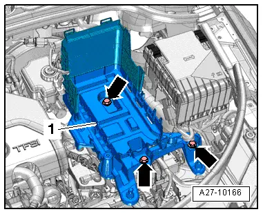
- Remove the bolts -arrows-.
- Remove the battery tray -1-.
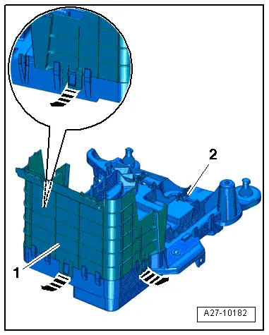
- Release the clips in direction of -arrows- and remove the rear battery jacket -1- on the battery tray -2-.
Installing
Install in reverse order of removal. Note the following:
- Install the battery. Refer to → Chapter "Battery in Engine Compartment, Removing and Installing, Version 1".
- Install the air filter housing. Refer to → Rep. Gr.23; Air Filter; Overview - Air Filter Housing or → Rep. Gr.24; Air Filter; Overview - Air Filter Housing.
Battery Tray, Removing and Installing, Version 2
Removing
- Remove the battery. Refer to → Chapter "Battery in Engine Compartment, Removing and Installing, Version 2".
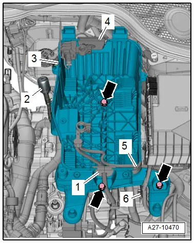
- Free up the grommets -1, 4 and 5- for the wire from the battery tray.
- Free up the wire from the battery tray.
- If equipped, free up the transmission ventilation -2- from the battery tray.
- Remove the bolts -arrows-.
- Remove the battery tray -3-.
Installing
Install in reverse order of removal. Note the following:
- Install the battery. Refer to → Chapter "Battery in Engine Compartment, Removing and Installing, Version 2".
READ NEXT:
 Battery, Charging
Preparing for Charging, Engine Compartment Battery
Procedure
WARNING
Risk of explosion on discharged battery with "Visual
indicator".
If the "Visual indicator" has no color or is light
Battery Jump Start Terminal
Overview - Battery Jump Start Terminal
1 - Bolt
6 Nm
2 - Battery Jump Start Terminal -U6-
With positive terminal grip
Removing and installing. Refer to
→ C
Start/Stop System
Component Location Overview - Start/Stop System
1 - Bracket
For the Voltage Stabilizer -J532-
2 - Connector
3 - Voltage Stabilizer -J532-
Removing and instSEE MORE:
Tire Requirements
A - Wet braking behavior
B - Comfort
C - Steering precision
D - Driving stability
E - Tire weight
F - Service life expectancy
G - Rolling resistance
H - Hydroplaning
The pie chart represents the tire's performa
Overview - Heater and A/C Unit Attachments and Air Intake Housing
Overview - Heater and A/C Unit Attachments and Air Intake Housing
1 - Sealing Plug
Equipment version
2 - Screw
1.5 Nm
3 - Screw
1.5 Nm
4 - Air Guide Channel to Left Footwell Vent
5 - Air Distribution Housing
The