Audi Q3: Tools and Equipment
Testing Equipment, Tools and Materials
General Information
 Note
Note
This list outlines the testers, tools and materials required for expert refrigerant circuit repair work.
- For tools and materials available from the distribution center or importer. Refer to → Chapter "Tools and Materials Available from Distribution Center or Importer".
- For commercially available tools and materials. Refer to → Chapter "Commercially Available Tools and Materials".
- For improvised tools. Refer to → Chapter "Improvised Tools".
Tools and Materials Available from Distribution Center or Importer
Commercially Available Tools and Materials
Improvised Tools

Tools and Materials Available from Distribution Center or Importer
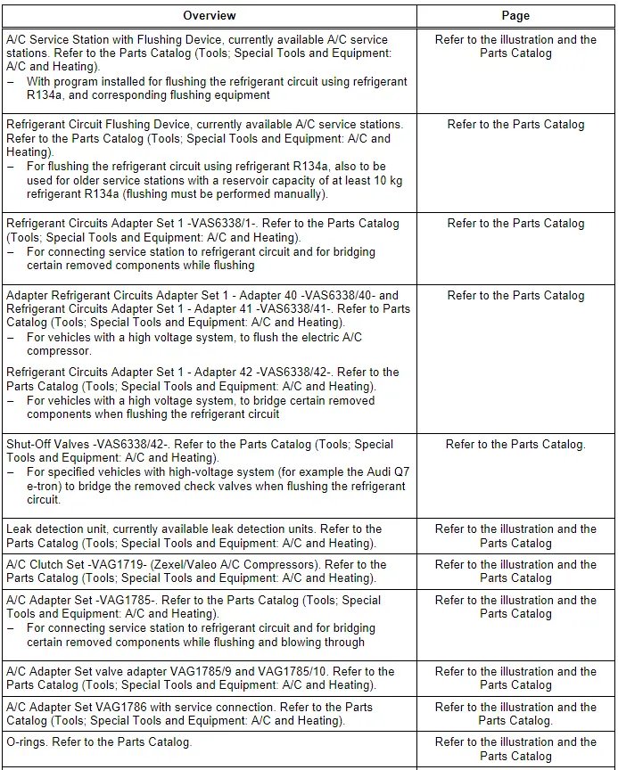
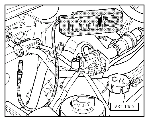
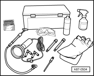
Service station/A/C Service Station (this illustration shows ), currently available A/C service stations. Refer to the Parts Catalog (Tools; Special Tools and Equipment: A/C and Heating).
- Work procedures: The operations "testing, extraction (recycling), evacuation and charging" are to be performed in line with the relevant operating instructions.
- The filters and dryers installed are to be replaced at the latest at the end of the period of use specified in the operating instructions and whenever the station has been drained (keep replacement filter to hand. Available from equipment manufacturer. Refer to A/C service station operating instructions.
- Use can also be made of service stations not described here. Refer to the Parts Catalog (Tools; Special Tools and Equipment: A/C and Heating).
- Currently available A/C service stations are equipped with a program for flushing the refrigerant circuit; the flushing equipment required for flushing is also included in delivery of these A/C Service Stations. Refer to the Parts Catalog (Tools; Special Tools and Equipment: A/C and Heating).
 Note
Note
- This A/C service station has the following known units: charging cylinder, pressure gauge set, vacuum pump, shutoff valves and charging hoses.
- One quick-release coupling each (for service connections on high and low-pressure side) is included in the scope of delivery of this service station.
- Current vacuum display (LED) appears after pressing the "Evacuate" button again.
Leak detection unit, currently available leak detection units. Refer to the Parts Catalog (Tools; Special Tools and Equipment: A/C and Heating).
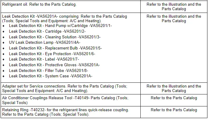
Leak detection system (for example Leak Detection Kit -VAS6201A-, currently available leak detection systems. Refer to the Parts Catalog (Tools; Special Tools and Equipment: A/C and Heating).
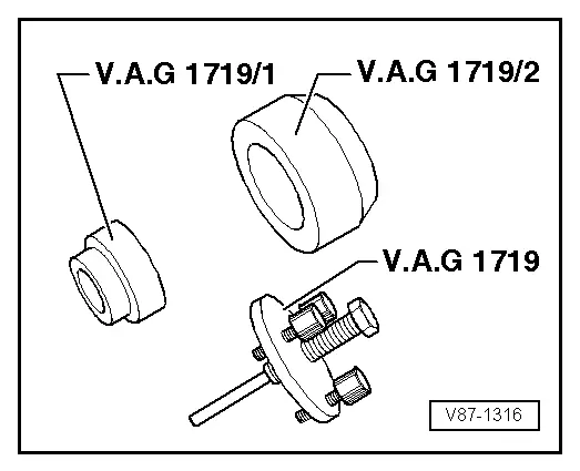
Puller for A/C Clutch Set -VAG1719- (for "Zexel" A/C compressor)
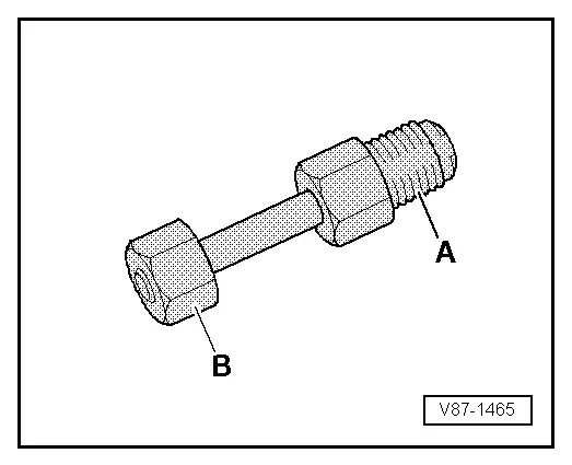
A/C Adapter Set -VAG1785-
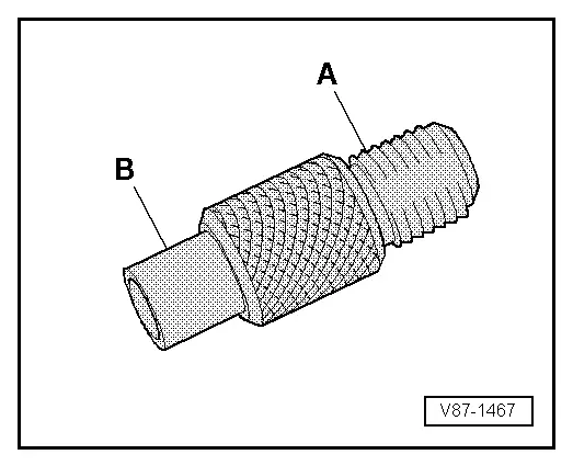
Adapter for cleaning refrigerant circuit (flush with refrigerant R134a. Refer to → Chapter "Refrigerant Circuit, Cleaning (Flushing), with Refrigerant R134a"; or blow through with compressed air and nitrogen. Refer to → Chapter "Refrigerant Circuit, Flushing with Compressed Air and Nitrogen".)
A - 5/8"-18 UNF thread for conical seal
B - Union nut (for connection with O-ring) with thread
- A/C Adapter Set - M18 x 1.5 -VAG1785/1-
- A/C Adapter Set - M20 x 1.5 -VAG1785/2-
- A/C Adapter Set - M24 x 1.5 -VAG1785/3-
- A/C Adapter Set - M28 x 1.5 -VAG1785/4-
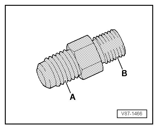
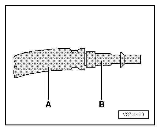
Adapter
A - 5/8"-18 UNF thread for conical seal
B - Threaded connection for O-ring
- A/C Adapter Set - M18 x 1.5 -VAG1785/5-
- A/C Adapter Set - M20 x 1.5 -VAG1785/6-
- A/C Adapter Set - M24 x 1.5 -VAG1785/7-
- A/C Adapter Set - M28 x 1.5 -VAG1785/8-
Valve adapter
A - 5/8"-18 UNF thread for conical seal
B - Internal thread with valve opener
- M10 x 1.25 VAG1785/9 (for connections with valve on high-pressure side)
- M10 x 1.5 VAG1785/10 (for connections with valve on high-pressure side)
 Note
Note
- A Schrader valve is screwed into connection -A-.
- A valve opener must be installed in the charging hose connection.
- Various adapters from adapter set are also part of the Refrigerant Circuits Adapter Set 1 -VAS6338/1-.
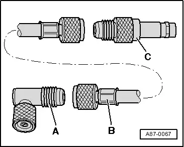
A/C Adapter Set -VAG1786-
A - A/C Adapter Set - Adapter 1 -VAG1786/1- (only for connections with small valve insert on low-pressure side)
B - Charging hose with union nut 5/8"-18 UNF (short version)
C - A/C Adapter Set - Adapter 2 -VAG1786/2-.
 Note
Note
- For connections with large valve insert (standard on "Zexel/Valeo" compressors, gradual change to small valve insert from 10/1994), use is to be made of adapter VAG1785/10 (remove valve from adapter VAG1785/10 or install valve opener in charging hose -B-).
- Beginning from production year 2006, the name of the "Zexel" A/C compressor was changed from "Zexel" to "Valeo".
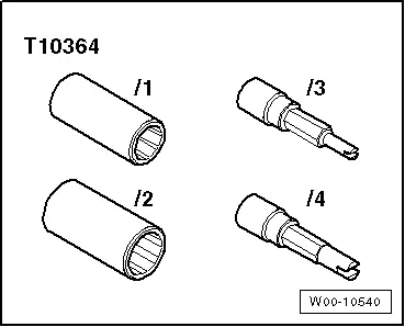
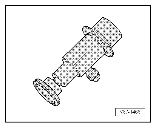
Refrigerant Sockets -T10364-
 Note
Note
For removing and installing service connections and valve units when the refrigerant circuit is empty.
Commercially Available Tools and Materials
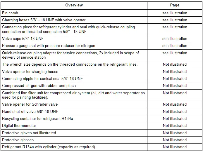
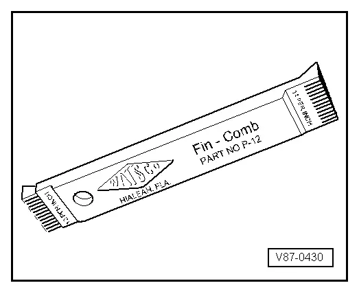
Fin comb
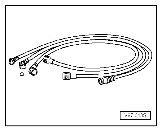
Fill hoses
5/8"-18 UNF thread
 Note
Note
- Use differently colored charging hoses (1800 mm long).
- Have valve opener and spare seals to hand.
- A charging hose in short version is also included in Refrigerant Circuits Adapter Set 1 -VAS6338/1-.
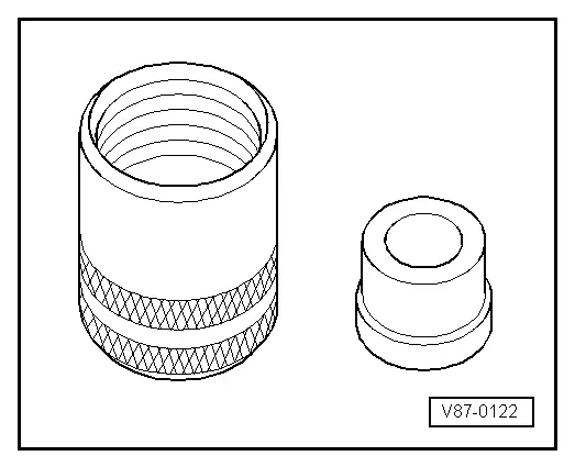
Connection piece for refrigerant cylinder with seal, quick-release coupling connection or threaded connection 5/8" - 18 UNF

Valve caps with spare seals (for 5/8"-18 UNF thread)
Seals can also be used for charging hoses.
 Note
Note
Valve caps with spare seals are also included in Refrigerant Circuits Adapter Set 1 -VAS6338/1-.
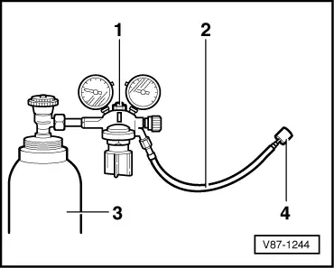
Pressure gauge set with pressure reducer for nitrogen (max. reducing pressure: 15 bar (218 psi) )
1 - Pressure gauge set
2 - Pressure hose (inner diameter 5 mm, length 2 m)
3 - Nitrogen
4 - Hose fitting
 Note
Note
For connection to A/C Adapter Set -VAG1785- with 5/8"-18 UNF thread.
Quick-release coupling adapter for service connections
- High-pressure side, nominal size 16 mm
- Low-pressure side, nominal size 13 mm
- 2x release tool (Sharan)
 Note
Note
This quick-release coupling is delivered with the service station.
Improvised Tools
Charging hose with connection for workshop compressed-air system
A - Charging hose 5/8" - 18 UNF (version with large inner diameter)
B - Connection for workshop compressed-air system (always use filter)
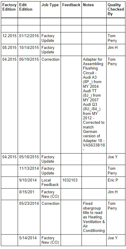
Revision History
DRUCK NUMBER: A0053300221
READ NEXT:
 Maintenance
Fluid Capacity Tables
Maintenance, diagnosis
Audi Q3
Caution
All quantities are approximate. Always refer to the
Repair Manual and/or the Maintenance Procedures for
correct filling iSEE MORE:
Setting the distance
Applies to: vehicles with adaptive cruise assist
Fig. 102 Operating lever: setting the distance
When approaching a vehicle driving ahead, the
adaptive cruise assist brakes to the set speed and
then maintains the set distance. If the vehicle
driving ahead accelerates, then the adaptive
cruise assist
Interior Door Mechanism, Removing and Installing
Removing
- Remove the rear door trim panel. Refer to
→ Chapter "Rear Door Trim Panel, Removing and Installing".
- Remove insulation mat.
- Disconnect and free up the connectors and wire.
- Remove the bolts -1- and
-2- from the rear of the door trim.
- Remove th