Audi Q3: Sensors
Overview - Front Axle Speed Sensor
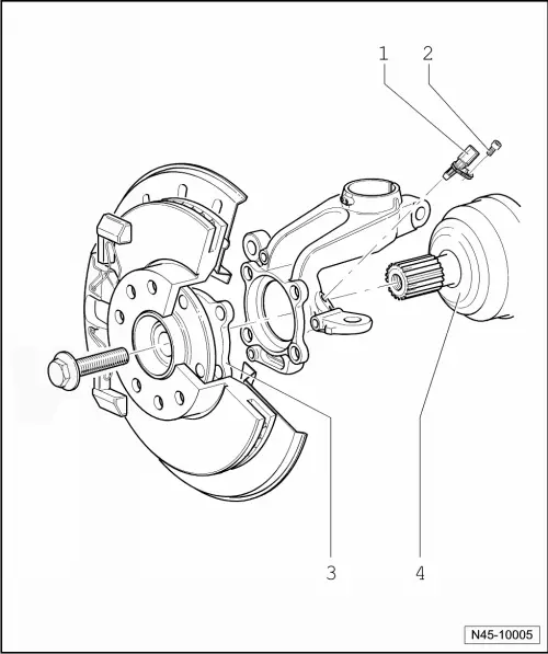
1 - Wheel Speed Sensor
- Right Front ABS Wheel Speed Sensor -G45-/Left Front ABS Wheel Speed Sensor -G47-
- Removing and installing, refer to → Chapter "Right/Left Front ABS Wheel Speed Sensor -G45-/-G47-, Removing and Installing".
2 - Bolt
- 8 Nm
3 - Wheel Hub with Wheel Bearing
- The ABS sensor ring is installed in the wheel bearing
4 - Drive Axle
Overview - Rear Axle Speed Sensor
Front Wheel Drive
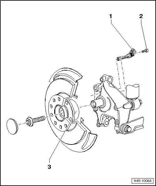
1 - Wheel Speed Sensor
- Right Rear ABS Wheel Speed Sensor -G44-/Left Rear ABS Wheel Speed Sensor -G46-
- Removing and installing, refer to → Chapter "Right/Left Rear ABS Wheel Speed Sensor -G44-/-G46-, Removing and Installing".
2 - Bolt
- 8 Nm
3 - Wheel Hub with Wheel Bearing
- The ABS sensor ring is installed in the wheel bearing
All Wheel Drive
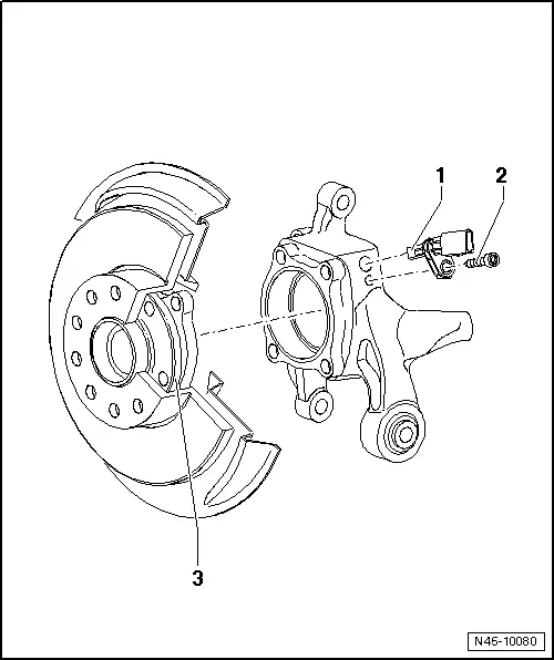
1 - Wheel Speed Sensor
- Right Rear ABS Wheel Speed Sensor -G44-/Left Rear ABS Wheel Speed Sensor -G46-
- Removing and installing, refer to → Chapter "Right/Left Rear ABS Wheel Speed Sensor -G44-/-G46-, Removing and Installing".
2 - Bolt
- 8 Nm
3 - Wheel Bearing
- The ABS sensor ring is installed in the wheel bearing
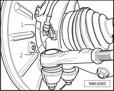
Right/Left Front ABS Wheel Speed Sensor -G45-/-G47-, Removing and Installing
Removing
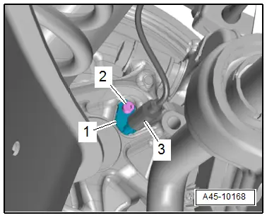
- Disconnect the connector -1- from the speed sensor wire and the speed sensor.
- Remove the bolt -2- and remove the speed sensor from the wheel bearing housing.
Installing
Install in reverse order of removal. Note the following:
- Before inserting speed sensor, clean the inner surface of the hole and coat the speed sensor all around with hot bolt paste. For the correct hot bolt paste, refer to the Parts Catalog.
Right/Left Rear ABS Wheel Speed Sensor -G44-/-G46-, Removing and Installing
Removing
Vehicles with FWD:
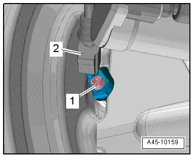
- Disconnect the connector -3- from the speed sensor wire and the speed sensor -1-.
- Remove the bolt -2- and remove the speed sensor from the wheel bearing housing.
AWD Vehicles:
- Disconnect the connector -1- from the speed sensor wire and the speed sensor.
- Remove the bolt -2- and remove the speed sensor from the wheel bearing housing.
Installing
Install in reverse order of removal. Note the following:
- Before inserting speed sensor, clean the inner surface of the hole and coat the speed sensor all around with hot bolt paste. For the correct hot bolt paste, refer to the Parts Catalog.
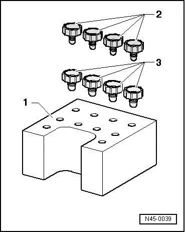
Special Tools
Special tools and workshop equipment required
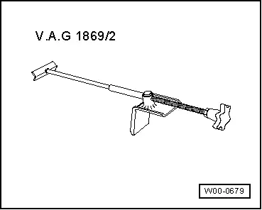
- Brake Pedal Actuator -VAG1869/2-.
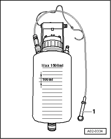
- Container -1- from the Brake Charger/Bleeder Unit -VAS5234-
- Plugs from Repair Kit -1H0 698 311 A-
READ NEXT:
 Overview - Front Brakes
Overview - Front Brakes, 1LJ 1ZD Brakes
1 - Bolt
12 Nm
2 - Brake Rotor
Allocation, refer to the Parts Catalog.
Dimensions, refer to
→ Chapter "Brakes
Front Brake Caliper Balance Weight
Depending on the model for each brake caliper two vibration
dampers are installed.
1 - Bolt
10 Nm
Replace after each removal.
2 - Vibration Damper
Installed 2 on SEE MORE:
Emergency call
Overview
Applies to: vehicles with emergency call function
An emergency call is a combination of data transmission
and a phone call. Your vehicle uses data
transmission to forward important information,
such as the vehicle and position data, to an emergency
call center.
Depending on the country an
Ball Joint, Removing and Installing
Special tools and workshop equipment
required
Puller - Ball Joint -3287A-
Digital Torque Wrench -VAG1756A-
Torque Wrench 1332 Insert - Ring Wrench - 18mm -VAG1332/10-
Removing
- Loosen drive axle bolt on the wheel hub. Refer to
→ Chapter "Drive Axle Threaded Connection, Lo