Audi Q3: Relay and Fuse Carriers Behind Instrument Panel on Driver Side, Removing and Installing
Relay Carrier on Vehicle Electrical System Control Module, Removing and Installing
Removing
- Remove the driver side instrument panel cover. Refer to → Body Interior; Rep. Gr.68; Storage Compartments/Covers; Driver Side Instrument Panel Cover, Removing and Installing.
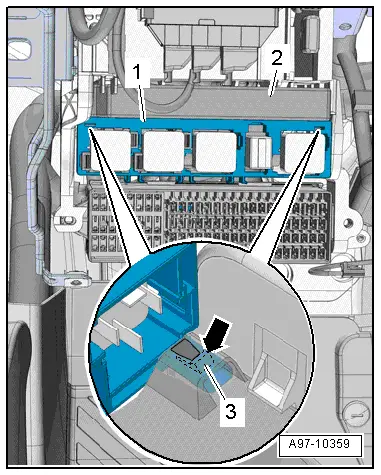
- Release the tab -3- with a screwdriver and remove the relay panel -2- from the vehicle electrical system control module -1-.
 Note
Note
Disregard -2-.
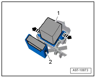
- Open the retainers in direction of -arrows- and remove the relay -1- and the control modules from the relay carriers.
 Note
Note
Check the exact assignment in the current wiring diagram. Refer to → Wiring diagrams, Troubleshooting & Component locations.

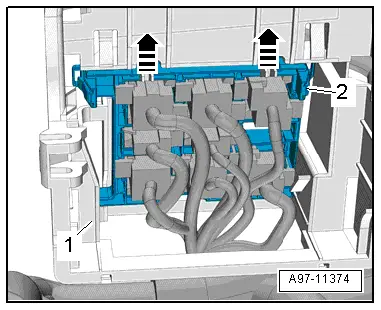
- Release the retainers -arrows- and remove the relay carrier -2- from the relay/fuse panel -1- to the rear.
Installing
Install in reverse order of removal. Note the following:
- Install the driver side instrument panel cover. Refer to → Body Interior; Rep. Gr.68; Storage Compartments/Covers; Driver Side Instrument Panel Cover, Removing and Installing.

Relay Carrier, Under Instrument Panel on Left Side, Removing and Installing
Removing
- Remove the vehicle electrical system control module. Refer to → Chapter "Vehicle Electrical System Control Module -J519-, Removing and Installing".
- Disengage the relay panel -2- from the mount -1- downward, to do this push the springs in the direction of -arrow-.
 Note
Note
Disregard -2-.
- Open the retainers -arrows- and remove the relay -1- and the control modules from the relay carriers.
 Note
Note
Check the exact assignment in the current wiring diagram. Refer to → Wiring diagrams, Troubleshooting & Component locations.
- Release the retainers -arrows- and remove the relay carrier -2- from the relay/fuse panel -1- to the rear.
Installing
Install in reverse order of removal. Note the following:
- Install the vehicle electrical system control module. Refer to → Chapter "Vehicle Electrical System Control Module -J519-, Removing and Installing".
Relay/Fuse Carrier Mount with Vehicle Electrical System Control Module -J519-, Removing and Installing
Removing
- Remove the fuse panel C and set aside with the wires still attached. Refer to → Chapter "Fuse Panel C -SC-, Removing and Installing".
- Remove the vehicle electrical system control module and set aside with the wires attached and if equipped with the relay carrier still attached. Refer to → Chapter "Vehicle Electrical System Control Module -J519-, Removing and Installing".
- Remove the relay carrier under left instrument panel. Refer to → Chapter "Relay Carrier, Under Instrument Panel on Left Side, Removing and Installing".
- Remove the instrument cluster. Refer to → Chapter "Instrument Cluster with Instrument Cluster Control Module -J285-, Removing and Installing".
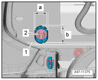
- To reach the upper nut -2- from the mount for the control modules, relay and fuse panel, drill an oblong hole into the instrument cluster mount -1- as shown.
- Dimension -a- = 22 mm.
- Dimension -b- = 23 mm.
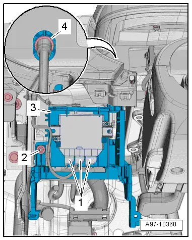
- Remove the nuts -2 and 4-.
- If equipped disconnect the connector -1- on the vehicle positioning system interface control module.
- If equipped disconnect the connector on the buzzer.
- Disengage the mount -3- for the control module, relay and fuse panel from the instrument panel central tube and remove.
Installing
Install in reverse order of removal. Note the following:
- Install the relay carrier under left instrument panel. Refer to → Chapter "Relay Carrier, Under Instrument Panel on Left Side, Removing and Installing".
- Install the vehicle electrical system control module. Refer to → Chapter "Vehicle Electrical System Control Module -J519-, Removing and Installing".
- Install fuse panel C. Refer to → Chapter "Fuse Panel C -SC-, Removing and Installing".
READ NEXT:
 Control Modules
Component Location Overview - Control Modules
Component Location Overview - Control Modules
1 - Vehicle Electrical System Control Module -J519-
Removing and installing. Refer to
â†
Connectors
Connector Component Location Overview
1 - Right Front Door Cut-Off Connector
Disconnecting. Refer to
→ Chapter "Left Door Cut-Off Connector, Disconnecting".
2 - SEE MORE:
Safety belts
General information
Each seat is equipped with a three-point safety
belt. Safety belts that are worn correctly are the
most effective way to reduce the risk of serious or
fatal injuries in a collision. Therefore, wear your
safety belt correctly and make sure that all vehicle
passengers are also wear
Driving through water
If you must drive through water, follow these instructions:
Check the stability of the ground, the current,
and the water depth. If the ground is unstable,
there is a strong current, or there are waves,
the water must only reach up to the lower edge
of the body at the most.
Deactivate the Sta