Audi Q3: Refrigerant Circuit
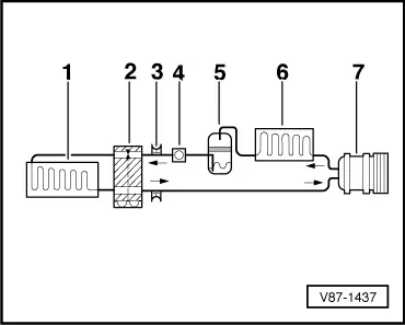
Refrigerant Circuit with Expansion Valve and Evaporator
The following illustration shows only the principle of a refrigerant circuit, the design of the refrigerant circuit in the respective vehicle can be found in the vehicle-specific repair manual. Refer to → Heating, Ventilation and Air Conditioning; Rep. Gr.87; Refrigerant Circuit; System Overview - Refrigerant Circuit.
1 - Evaporator
2 - Expansion Valve
3 - Valve for extracting, filling and measuring
4 - Sight glass (not installed in R134a circuits)
5 - Receiver/dryer with dryer
6 - Condenser
7 - A/C Compressor
 Note
Note
Arrows point in direction of refrigerant flow.
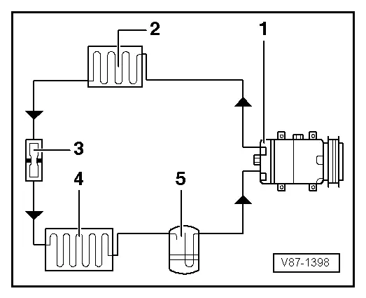
Refrigerant Circuit with Restrictor and Reservoir
The following illustration shows only the principle of a refrigerant circuit, the design of the refrigerant circuit in the respective vehicle can be found in the vehicle-specific repair manual. Refer to → Heating, Ventilation and Air Conditioning; Rep. Gr.87; Refrigerant Circuit; System Overview - Refrigerant Circuit.
1 - A/C Compressor
2 - Condenser
3 - Restrictor
4 - Evaporator
5 - Reservoir
 Note
Note
Arrows point in direction of refrigerant flow.
Refrigerant Circuit with an Electrically Driven A/C Compressor (with and without Battery Cooling Module)
Vehicles with a high-voltage system (hybrid vehicles)
Extremely Dangerous Due to High-Voltage
The high-voltage system is under high-voltage. Death or serious bodily injury by electric shock.
- Individuals with electronic/medical life- and health sustaining machines in or on their person cannot perform any work on high-voltage systems. Life- and health sustaining machines are for example pain killer pumps, implanted defibrillators, pacemakers, insulin pumps, and hearing aids.
- Have the high-voltage system de-energized by a qualified person.
There is a Risk of Injury from the Engine Starting Unexpectedly
On electric - hybrid vehicles an active ready mode is difficult to identify. Parts of the body can be clamped or pulled.
- Turn off the ignition.
- Place the ignition key outside of the vehicle interior.
Risk of Damaging the High-Voltage Cables
Misuse can damage the insulation of high-voltage cables or high-voltage connectors.
- Never support objects on the high-voltage cables and the high-voltage connectors.
- Never support tools on the high-voltage cables and the high-voltage connectors.
- Never sharply bend or kink the high-voltage cables.
- When connecting pay attention to the coding of the high-voltage connectors.
- For all procedures on vehicles with high-voltage system pay attention to the additional warning message for these vehicles. Refer to → Chapter "Warnings when Working on Vehicles with High Voltage System".
- If procedures are necessary near components of the high-voltage system "perform a visual inspection of the damage of the high-voltage components and lines". Refer to → Chapter "Performing a Visual Inspection of Damage to High Voltage Components and Cables".
- If work on the components of the high-voltage system is necessity, de-energize the high-voltage system. Refer to → Rep. Gr.93; High-Voltage System, De-Energizing or → Electrical Equipment; Rep. Gr.93; High-Voltage System, De-Energizing.
 Note
Note
The following illustration shows a refrigerant circuit as an example, as it is installed in an Audi Q5 hybrid, for the design of the refrigerant circuit in the respective vehicle refer to the vehicle-specific repair manual. Refer to → Heating, Ventilation and Air Conditioning; Rep. Gr.87; Refrigerant Circuit; System Overview - Refrigerant Circuit.
-Arrows- point in direction of refrigerant flow.
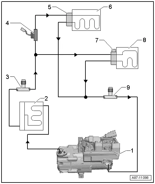
1 - Electrically-Driven A/C Compressor
- With A/C Compressor Control Module -J842- and Electrical A/C Compressor -V470-
2 - Condenser
- With receiver/dryer and dryer cartridge
3 - Service Connection, HP side
4 - Hybrid Battery Refrigerant Shut-Off Valve 1 -N516-
- Only for vehicles with a battery cooling module for the Hybrid Battery Unit -AX1-.
 Note
Note
The Hybrid Battery Refrigerant Shut-Off Valve 1 -N516- is activated, for example, if it is necessary to cool the battery and no cooling is desired in the passenger compartment (open without activation).
5 - Expansion Valve
- On the evaporator in the A/C system
6 - Evaporator
- Evaporator in the A/C System
7 - Expansion Valve with Hybrid Battery Refrigerant Shut-Off Valve 2 -N517-
- On the evaporator in the battery cooling module
- Only for vehicles with a battery cooling module for the Hybrid Battery Unit -AX1-.
 Note
Note
The Hybrid Battery Refrigerant Shut-Off Valve 2 -N517- is activated if it is necessary to cool the battery (closed without activation).
8 - Evaporator
- Evaporator in the battery cooling module
- Only for vehicles with a battery cooling module for the Hybrid Battery Unit -AX1-.
9 - Service Connection, LP Side
READ NEXT:
 Connections for Quick-Release Coupling on Refrigerant Circuit
General Information
Only valves and connections that are resistant to
refrigerant R134a and refrigerant oil must be installed.
Different connections (outer diameter) for high pressure and
lo
Switches and Sensors on Refrigerant Circuit and Connections
A/C Refrigerant High Pressure Switch -F23-
Note
Switch pressures, removing and installing switches as well
as switch arrangement and version. Refer to vehicle specific
refrigerant circu
Refrigerant Circuit Pressures and Temperatures
General Information
Caution
When performing work on refrigerant circuit, observe
all generally applicable safety precautions and pressure
container regulations.
The pressures and tempSEE MORE:
Overview - Front Three-Point Seat Belt
Overview - Front Three-Point Seat Belt, USA and Canada Market
1 - Belt End Fitting Cover
Removing and installing. Refer to
→ Chapter "Front Belt End Fitting, Removing and Installing, USA and
Canada Market-Specific".
2 - Bolt
45 Nm
If it was removed
Air Quality Sensor -G238-, Removing and Installing
Removing
- Remove the plenum chamber cover. Refer to
→ Body Exterior; Rep. Gr.50; Bulkhead; Plenum Chamber Cover,
Removing and Installing.
- Release the securing tab -4-
and turn the housing -1- for the
Air Quality Sensor -G238- counter-clockwise
-arrow-.
- 