Audi Q3: Rear Brake Caliper
Overview - Rear Brake Caliper
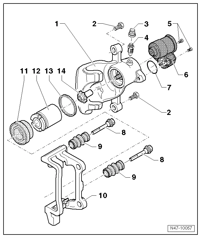
1 - Brake Caliper
- Pre-bleed brake caliper after repairing, refer to → Chapter "Hydraulic System, Pre-Bleeding".
2 - Bolt
- 35 Nm
- Replacing
- Self-locking
- When loosening and tightening, counter-hold at guide pin
3 - Dust Cap
4 - Bleeder Screw
- 13 Nm
- Before installing, lightly grease the thread with Lithium Grease -G 052 150 A2-.
5 - Bolt
- Tightening specification, refer to item -14-.
6 - Parking Brake Motor
7 - Seal
8 - Guide Pin
- Grease before pulling on protective cap
9 - Protective Cap
- Install on brake carrier and guide pin.
10 - Brake Carrier with Guide Pins and Cap
- Supplied as an assembled replacement part with sufficient grease on guide pins.
- Install the repair kit if the caps or guide pins are damaged. Use supplied grease packet to lubricate guide pins.
11 - Protective Cap
- Pull onto piston with outer sealing lip
- Removing and installing, refer to → Chapter "Brake Caliper Piston, Removing and Installing".
12 - Piston
- Removing and installing, refer to → Chapter "Brake Caliper Piston, Removing and Installing".
- Thinly coat the piston with Lithium Grease -G 052 150 A2-
13 - Seal
- Do not damage when installing piston
- Removing and installing, refer to → Chapter "Brake Caliper Piston, Removing and Installing".
14 - Pressure Nut
Brake Caliper Piston, Removing and Installing
Special tools and workshop equipment required
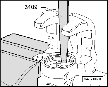
- Trim Removal Wedge -3409-
Removing
- The brake caliper is removed, refer to → Chapter "Brake Caliper, Replacing".
- The parking brake motor is removed, refer to → Chapter "Left/Right Parking Brake Motor -V282-/-V283-, Removing and Installing".
 Note
Note
- Install complete repair kit when servicing.
- To clean the brakes only use mineral spirits.
- Thinly coat the brake cylinder, piston and seal with Lithium Grease -G 052 150 A2-.
- In case of repair, brake calipers must always be pre-bled before being installed into vehicle (without brake pads), refer to → Chapter "Hydraulic System, Pre-Bleeding".
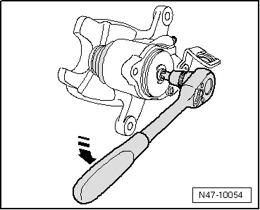
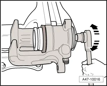
- Using an 8 mm internal multi-point socket, turn the spindle counter-clockwise in direction of -arrow-. As a result, the thrust nut pushes the piston out of the brake caliper.
- Remove the piston with the protective cap from the brake caliper.
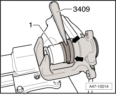
- Remove the sealing ring using the Trim Removal Wedge -3409-.
- Clean the surfaces on the pistons and seal only with mineral spirits and then dry.
Installing
- Thinly coat the piston and the seal with Lithium Grease -G 052 150 A2- before installing.
- Insert oil seal into brake caliper.
- Place protective cap with outer sealing lip on piston.
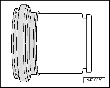
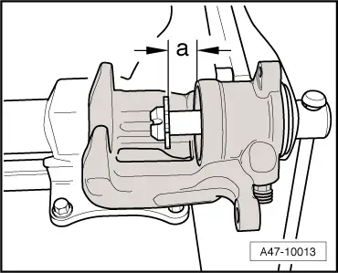
- Turn the thrust nut far enough onto the spindle so that the dimension -a- = 15 mm is reached.
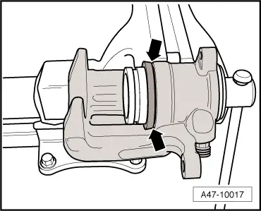
- Insert the inner sealing lip of the protective cap into the groove -arrows- in the brake caliper using the Trim Removal Wedge -3409-.
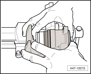
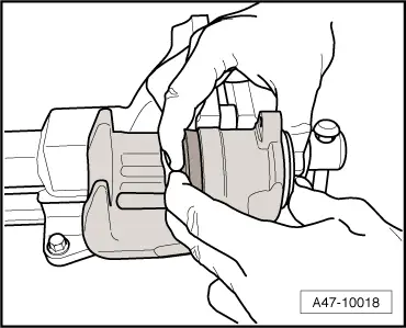
- Slide the piston onto the thrust nut, which is only possible in four positions.
- Carefully press the piston into the brake caliper by moving the piston.
- Press the piston far enough into the brake caliper until it touches the thrust nut.
- Carefully turn the spindle clockwise in direction of -arrows- until the thrust nut is at the stop.
- The protective cap must contact the brake caliper -arrows- all the way around.
- Press the piston into the brake caliper by hand
- Outer sealing lip of protective cap will then engage in piston groove.
READ NEXT:
 Overview - Brake Booster/Master Brake Cylinder
Note
Brake master cylinder and brake boosters can be replaced
independently of one another.
1 - Heat Shield
2 - Nut
25 Nm
Always replace if removed
Sel
Brake Lamp Switch, Removing and Installing
Note
The Brake Lamp Switch -F-/Brake Pedal Switch -F63- is
installed in the brake master cylinder.
Removing
Audi RS Q3:
- Remove the air filter housing, refer to
→ Engine
Brake Master Cylinder, Removing and Installing
Special tools and workshop equipment
required
Brake Charger/Bleeder Unit -VAS5234-
Sealing plugs from Repair Kit -1H0 698 311 A-
Removing
- Remove the brake fluid reservoir,SEE MORE:
Overview - Seat Pan, Drawer
1 - Retaining Tab
2 - Drawer
3 - Bolt
1.5 Nm
4 - Bolt
1.5 Nm
5 - Mount
For the drawer
Removing and installing. Refer to
→ Chapter "Drawer Mount, Removing and Installing".
Overview - Seat Pan, Storage Compartment
Specifications for Retrofitting Wheel and Tire Combinations (Documents)
Legal Requirements
The manufacturer is granted general type approval for the
whole vehicle including all parts and for specific retrofitting
(general type approval according to 20 StVZO (Motor Vehicle
Construction and Use Regulations or EU type approval).
Retrofitting to wheels and tires ca