Audi Q3: Overview - Subframe
Suspension, Wheels, Steering / Chassis / Audi Q3 (8U) 2011-2018 Service Manual / Overview - Subframe
Overview - Subframe, Vehicles with FWD
 Caution
There is a risk of damaging the subframe threaded connection threads on the body.
- The subframe bolts on the body must not be loosened or tightened with an impact wrench.
- Always install all bolts by hand for the first few turns.
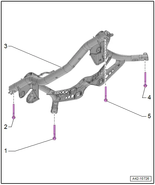
1 - Bolt
- 90 Nm + 90º
- Always replace if removed
2 - Subframe
- Removing and installing. Refer to → Chapter "Subframe, Removing and installing, FWD Vehicles".
3 - Bolt
- 90 Nm + 90º
- Always replace if removed
4 - Bolt
- 90 Nm + 90º
- Always replace if removed
5 - Bolt
- 90 Nm + 90º
- Always replace if removed
Overview - Subframe, Vehicles with AWD
 Caution
There is a risk of damaging the subframe threaded connection threads on the body.
- The subframe bolts on the body must not be loosened or tightened with an impact wrench.
- Always install all bolts by hand for the first few turns.
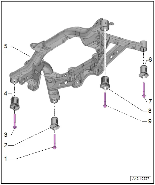
1 - Bolt
- 90 Nm +90º
- Always replace if removed
2 - Bonded Rubber Bushing
- Replacing. Refer to → Chapter "Subframe, Servicing".
3 - Bolt
- 90 Nm +90º
- Always replace if removed
4 - Bonded Rubber Bushing
- Replacing. Refer to → Chapter "Subframe, Servicing".
5 - Subframe
- Removing and installing. Refer to → Chapter "Subframe, Removing and Installing, AWD Vehicles".
- 6 - Bonded Rubber Bushing
- Replacing. Refer to → Chapter "Subframe, Servicing".
7 - Bolt
- 90 Nm +90º
- Always replace if removed
8 - Bonded Rubber Bushing
- Replacing. Refer to → Chapter "Subframe, Servicing".
9 - Bolt
- 90 Nm +90º
- Always replace if removed
READ NEXT:
 Subframe, Removing and Installing
Subframe, Removing and installing, FWD Vehicles
Special tools and workshop equipment
required
Locating Pins -T10096-
Torque Wrench 1332 40-200Nm -VAG1332-
Engine and Gearbox Jack -VAS6931-
Subframe, Servicing
Tools and Preliminary Work
Special tools and workshop equipment
required
Hydraulic Press -VAS6178-
with Bearing Installer - Wheel Hub/Bearing Kit - Pressure
Head -T10205/13- from the Bearin
Stabilizer Bar
Overview - Stabilizer Bar
1 - Subframe
2 - Bolt
25 Nm + 45º
Always replace if removed
Install evenly
3 - Clamp
4 - Bearing
Always replace tSEE MORE:
Entering a destination
Intelligent search for navigation destinations
Applies to: vehicles with navigation system
Using the intelligent search, you can enter the
data for a navigation destination in any order all
at once (for example, 5th Avenue New York).
Likewise, you can search for points of interest,
contacts, previo
Satellite map
Applies to: vehicles with navigation system and satellite map
You can display the navigation map with satellite
images.
Requirement: the MMI must be connected to the
Internet.
Applies to: MMI: Select on the home screen:
NAVIGATION > > Map settings >
Satellite
map1).
The map view is
© 2019-2026 Copyright www.auq3.net | 0.01
