Audi Q3: Overview - Brake Booster/Master Brake Cylinder
Brake System / Chassis / Audi Q3 (8U) 2011-2018 Service Manual / Overview - Brake Booster/Master Brake Cylinder
 Note
Note
Brake master cylinder and brake boosters can be replaced independently of one another.
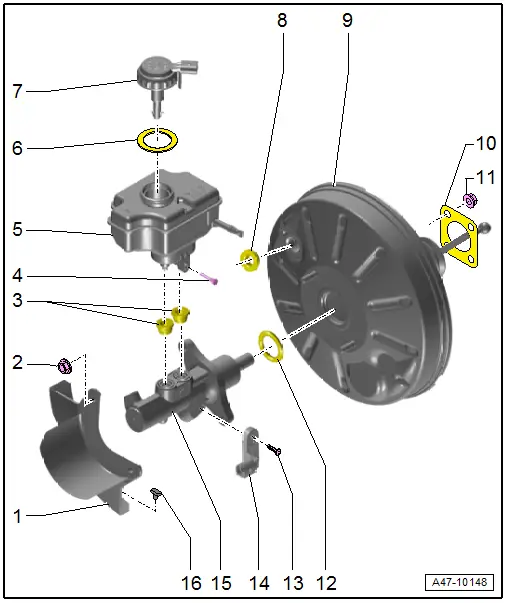
1 - Heat Shield
2 - Nut
- 25 Nm
- Always replace if removed
- Self-locking
3 - Sealing Plug
- Coat with brake fluid and press into brake fluid reservoir
4 - Bolt
- 5 Nm
5 - Brake Fluid Reservoir
- Removing and installing, refer to → Chapter "Brake Fluid Reservoir, Removing and Installing".
6 - Seal
7 - Cap
8 - Grommet
9 - Brake Booster
- Functional check:
- With engine switched off, depress brake pedal firmly several times (to exhaust the vacuum in the unit).
- Depress and hold brake pedal with average foot pressure and start engine. If brake booster is working properly, pedal will be felt to give noticeably under foot (booster assistance becomes effective).
- Disconnect from brake pedal, refer to → Chapter "Brake Pedal, Removing from Brake Booster".
- Removing and installing, refer to → Chapter "Brake Booster, Removing and Installing".
10 - Seal
- For brake booster
11 - Nut
- Tightening specification and sequence, refer to item -2-.
12 - Seal
- Replace after removing
13 - Bolt
- 5 Nm
14 - Brake Lamp Switch -F-/Brake Pedal Switch -F63-
- Removing and installing, refer to → Chapter "Brake Lamp Switch, Removing and Installing".
15 - Brake Master Cylinder
- Cannot be serviced
- If malfunctioning: replace as complete unit.
- Removing and installing, refer to → Chapter "Brake Master Cylinder, Removing and Installing".
16 - Rubber Buffer
READ NEXT:
 Brake Lamp Switch, Removing and Installing
Note
The Brake Lamp Switch -F-/Brake Pedal Switch -F63- is
installed in the brake master cylinder.
Removing
Audi RS Q3:
- Remove the air filter housing, refer to
→ Engine
Brake Master Cylinder, Removing and Installing
Special tools and workshop equipment
required
Brake Charger/Bleeder Unit -VAS5234-
Sealing plugs from Repair Kit -1H0 698 311 A-
Removing
- Remove the brake fluid reservoir,
Overview - Electric Vacuum Pump
1 - Brake System Vacuum Pump -V192-
Allocation, refer to the Parts Catalog.
Installed location: in the engine compartment over the engine
transmission separating point.
Do not diSEE MORE:
Traffic light information
Description
Applies to: vehicles with traffic light information
Fig. 93 Instrument cluster: traffic light information display
The traffic light information gives you a speed
recommendation in order to reach the next traffic
light when it is green 1, or it informs you of
the wait time at the next re
Control Module/Digital Sound System Amplifier, Removing and Installing
The Digital Sound System Control Module -J525- in the right
rear of the luggage compartment under the luggage compartment
floor covering.
Note
If replacing the control module, select the "Replace control
module" function for the corresponding control module on the
Vehicle Diagnost
© 2019-2026 Copyright www.auq3.net | 0.0104
