Audi Q3: Light Switch -E1-, Removing and Installing
Removing
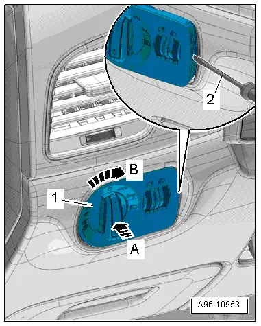
- Turn the light switch to position "0".
- Push the light switch in direction of -arrow A- and turn right at the same time in direction of -arrow B-.
- Hold the switch in this position ad at the same time remove the light switch from the switch housing -1-, to do this open the tab on the opening -2- with a narrow screwdriver.
- Disconnect the connectors.
Installing
Install in reverse order of removal. Note the following:
- Push the switch into the switch housing until it clicks into place.
Instrument Panel and Switch Illumination Dimmer Switch -E20-, Removing and Installing
Depending on vehicle equipment, the Instrument Panel Illumination Dimmer Switch -E20-, and the Headlamp Adjuster -E102- are in the same housing. They cannot be replaced separately if faulty; allocation. Refer to the Parts Catalog.
Removing
- Remove the light switch. Refer to → Chapter "Light Switch -E1-, Removing and Installing".
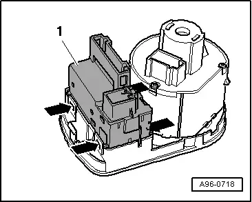
- Open the clip -arrows- and remove the housing -1-.
Installing
Install in reverse order of removal. Note the following:
- Install the light switch. Refer to → Chapter "Light Switch -E1-, Removing and Installing".
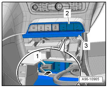
ASR/ESP Button -E256-, Removing and Installing
Removing
- Remove the A/C system control head. Refer to → Heating Ventilation and Air Conditioning; Rep. Gr.87; Display And Control Unit, Removing and Installing.
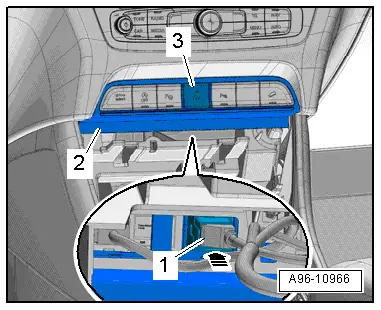
- Push out the button -3- through the opening behind the mount -2- in direction of -arrow-.
- Disconnect the connector -1-.
Installing
Install in reverse order of removal. Note the following:
- Install the A/C system control head. Refer to → Heating Ventilation and Air Conditioning; Rep. Gr.87; Display And Control Unit, Removing and Installing.
Instrument Panel Button, Removing and Installing
Lower Left Instrument Panel Button Unit, Removing and Installing
Removing
- Remove the A/C system control head. Refer to → Heating Ventilation and Air Conditioning; Rep. Gr.87; Display And Control Unit, Removing and Installing.
- Push out the button unit -3- through the opening behind the mount -2- in direction of -arrow-.
- Disconnect the connector -1-.
Installing
Install in reverse order of removal. Note the following:
- Install the A/C system control head. Refer to → Heating Ventilation and Air Conditioning; Rep. Gr.87; Display And Control Unit, Removing and Installing.
Lower Right Instrument Panel Button Unit, Removing and Installing
Removing
- Remove the A/C system control head. Refer to → Heating Ventilation and Air Conditioning; Rep. Gr.87; Display And Control Unit, Removing and Installing.
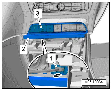
- Push out the button unit -2- through the opening behind the mount -3- in direction of -arrow-.
- Disconnect the connector -1-.
Installing
Install in reverse order of removal. Note the following:
- Install the A/C system control head. Refer to → Heating Ventilation and Air Conditioning; Rep. Gr.87; Display And Control Unit, Removing and Installing.
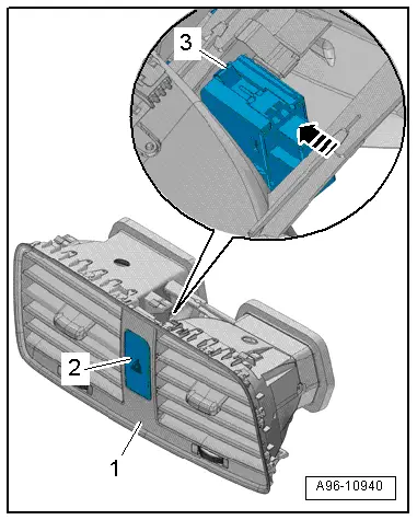
Emergency Flasher Button -E229-, Removing and Installing
Removing
- Remove the center instrument vent. Refer to → Body Interior; Rep. Gr.70; Instrument Panel; Instrument Panel Vent, Removing and Installing.
- Open the upper and lower clip -3-.
- Remove the emergency flasher button -2- from the instrument panel vent -1- in direction of -arrow-.
Installing
Install in reverse order of removal. Note the following:
- Install the center instrument vent. Refer to → Body Interior; Rep. Gr.70; Instrument Panel; Instrument Panel Vent, Removing and Installing.
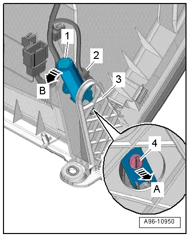
Glove Compartment Lamp Switch -E26-, Removing and Installing
Removing
- Remove the glove compartment. Refer to → Body Exterior; Rep. Gr.68; Storage Compartment/Covers; Glove Compartment, Removing and Installing.
- Disconnect the connector -2-.
- Remove the hinge bolts -4- in direction of -arrow A-.
- Release the switch -1- counter-clockwise in direction of -arrow B-.
- Remove the switch, to do this push the outer mount -3- slightly to the side.
Installing
Install in reverse order of removal. Note the following:
- Install the glove compartment. Refer to → Body Exterior; Rep. Gr.68; Storage Compartment/Covers; Glove Compartment, Removing and Installing.
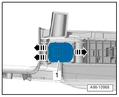
Mirror Adjusting Switch -E43-/Folding Mirror Adjustment Switch -E168-, Removing and Installing
Removing
- Remove the pull handle with the switch mount. Refer to → Body Interior; Rep. Gr.70; Door Trim Panels; Front Pull Handle, Removing and Installing.
- Release the hooks in direction of -arrows- carefully with a small screwdriver.
- Press the mirror adjusting switch -1- out of the switch mount.
Installing
Install in reverse order of removal. Note the following:
 Note
Note
When installing, ensure symbol panel is inserted in front of mirror adjusting switch.
- Install the armrest. Refer to → Body Interior; Rep. Gr.70; Front Door Trim Panels; Front Pull Handle Removing and Installing.
READ NEXT:
 Power Window Control Head In Driver Door -E512-, Removing and Installing
Removing
- Remove the pull handle with the switch mount. Refer to
→ Body Interior; Rep. Gr.70; Door Trim Panels; Front Pull
Handle, Removing and Installing.
- Carefully
Rear Lid Lock Cylinder Unlock Button -F248-, Removing and Installing
Removing
- Remove the rear lid trim panel. Refer to
→ Body Interior; Rep. Gr.70; Luggage Compartment Trim Panels;
Rear Lid Lower Trim Panel, Removing and Installing.
-
Anti-Theft Alarm System
Overview - Interior Monitoring
1 - Nut
7 Nm
2 - Bracket
For Alarm Horn -H12-
3 - Alarm Horn -H12-
Removing and installing. Refer to
→ CSEE MORE:
Roof Bars/Roof Rails
Overview - Roof Railing
1 - Nut
Quantity: 4
Install with locking compound. For the correct locking compound,
refer to the Parts Catalog.
Tightening sequence. Refer to
→ Fig. "Roof Rail - Tightening Specification and Sequence"
2 - Balancing Element
Quan
Component Location Overview - Instrument Panel Lamps
1 - Center Instrument Panel Vent Illumination Bulb -L68-
integrated in the center instrument panel vent Cannot be replaced
separately if faulty.
Center Instrument Panel Vent, removing and installing. Refer to
→ Body Interior; Rep. Gr.70; Instrument Panel; Instru