Audi Q3: Left Temperature Door Motor -V158-, Removing and Installing
 Note
Note
- Only on vehicles with an automatic climate control system
- For vehicles with a manual climate control system (or heater without Air Conditioning (A/C) system), the temperature doors are actuated by the Temperature Regulator Door Motor -V68-. The right and left temperature doors are connected to each other via the shaft.
- The color-coded connecting elements on the actuator for the identification has been discontinued as a running change as of 10/2013 for those connecting elements installed by the manufacturer and delivered as a replacement part. Additionally the connecting elements are no longer preinstalled on actuators that are delivered as a replacement part. Refer to → Chapter "Actuator Information" and the Parts Catalog.
- The actuators and the associated connecting elements differ. In some cases, however, the differences are so small that they are not always easy to detect at first glance. If a different version of the actuator or a connecting element is installed than the designated version, it usually leads to problems when the basic setting is to be performed. Refer to → Chapter "Actuator Information" and the Vehicle Diagnostic Tester in the "Guided Fault Finding" function.
 Caution
Problems with the A/C system (heater) function after installing the incorrect version of components
- Different actuator versions can only be distinguished by their part number on the outside.
- The connecting elements are to some extent very similar and are not always easy to detect at first glance.
- If possible, only install an actuator if the new component to be installed is available with the related connecting element.
- Before installing, make sure that the actuator is the right one and the connecting element being installed is correctly allocated.
- If possible, only dispose of the removed components after having checked the function of the newly installed components.
Removing
- Note the general information. Refer to → Chapter "Actuator Information".
- Remove the instrument panel. Refer to → Body Interior; Rep. Gr.70; Instrument Panel; Instrument Panel, Removing and Installing.
- Remove the data bus on board diagnostic interface. Refer to → Electrical Equipment; Rep. Gr.97; Control Modules; Data Bus On Board Diagnostic InterfaceJ533, Removing and Installing.
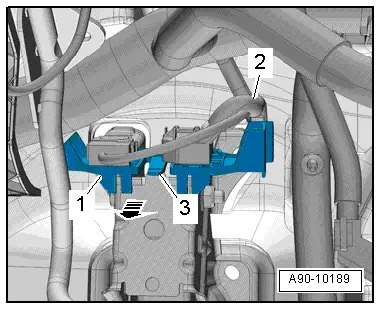
- Free up the wiring harness -2-.
- Release the tab -3- and remove the mount -1- from the pedal assembly -arrow-.
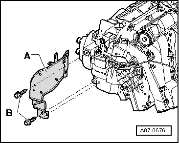
- Remove the bolts -B-.
- Free up the wiring harness on the bracket -A-, disengage the cable channel and move to the side.
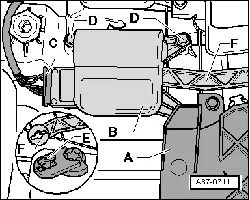
- Remove the bolts -D-.
- Push the heater core cover -A- slightly to the side at top and remove the actuator -B- from the temperature door shaft.
- Mark the connector and the actuator.
- Disconnect the connector -C-.
- Loosen the connecting rod -F- from the actuator operating lever -E-.
- Turn the actuator so far until the operating lever opening and the latch on the operating lever align.
- Remove the actuator from the operating lever.
Installing
Installation is done is reverse order, observe the following:
- Pry out the connecting element (here the operating lever -E-) from the actuator to be replaced (or select from the set of connecting elements) and install in the new actuator to be installed. Refer to → Chapter "Actuator Information".
- Install the actuator operating lever on the connecting rod -F-.
- The mount for the connecting rod -F- can only be installed in one position on the operating lever -E-.
- The mount for the connecting rod -F- must align with the operating lever -E- as shown in the illustration.
 Note
Note
If the mount for the connecting rod -F- and the operating lever -E- do not align, turn the mount in the actuator. Note the general information. Refer to → Chapter "Actuator Information".
- Connect the connector.
- Attach the actuator to the air distribution housing.
- There must not be any play in the connection between the actuator, shaft and connecting rod -F-.
- Carefully tighten the screws (tightening specification 1 Nm).
- Install the wiring harness so that it cannot come in contact with any moving parts (for example, the lever on the actuator).
- Install the data bus on board diagnostic interface. Refer to → Electrical Equipment; Rep. Gr.97; Control Modules; Data Bus On Board Diagnostic InterfaceJ533, Removing and Installing.
- Install the instrument panel. Refer to → Body Interior; Rep. Gr.70; Instrument Panel; Instrument Panel, Removing and Installing.
After completing the repair work, perform the following operations on the control head using the Vehicle Diagnostic Tester in the "Guided Fault Finding" function:
- Check the DTC memory and delete any currently displayed entries.
- Perform the basic setting.
- Perform output diagnostic test mode (DTM).
Right Temperature Door Motor -V159-, Removing and Installing
 Note
Note
- Only on vehicles with an automatic climate control system
- For vehicles with a manual climate control system (or heater without A/C system), the temperature doors are actuated by the Temperature Regulator Door Motor -V68-. The right and left temperature doors are connected to each other via the shaft.
- The color-coded connecting elements on the actuator for the identification has been discontinued as a running change as of 10/2013 for those connecting elements installed by the manufacturer and delivered as a replacement part. Additionally the connecting elements are no longer preinstalled on actuators that are delivered as a replacement part. Refer to → Chapter "Actuator Information" and the Parts Catalog.
- The actuators and the associated connecting elements differ. In some cases, however, the differences are so small that they are not always easy to detect at first glance. If a different version of the actuator or a connecting element is installed than the designated version, it usually leads to problems when the basic setting is to be performed. Refer to → Chapter "Actuator Information" and the Vehicle Diagnostic Tester in the "Guided Fault Finding" function.
 Caution
Problems with the Air Conditioning (A/C) system (heater) function after installing the incorrect version of components
- Different actuator versions can only be distinguished by their part number on the outside.
- The connecting elements are to some extent very similar and are not always easy to detect at first glance.
- If possible, only install an actuator if the new component to be installed is available with the related connecting element.
- Before installing, make sure that the actuator is the right one and the connecting element being installed is correctly allocated.
- If possible, only dispose of the removed components after having checked the function of the newly installed components.
Removing
- Note the general information. Refer to → Chapter "Actuator Information".
- Remove the glove compartment. Refer to → Body Interior; Rep. Gr.68; Storage Compartments and Covers; Glove Compartment, Removing and Installing.
- Remove the footwell vent on the front passenger side. Refer to → Chapter "Front Passenger Side Footwell Vent, Removing and Installing".
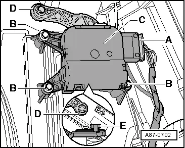
- Mark the connector and the actuator.
- Remove the bolts -B-.
- Remove the actuator -C- from the temperature door shaft.
- Disconnect the connector -A-.
- Loosen the connecting rod -D- from the actuator operating lever -E-.
- Turn the actuator so far until the operating lever opening and the latch on the operating lever align.
- Remove the actuator from the operating lever.
Installing
Installation is done is reverse order, observe the following:
- Pry out the connecting element (here the operating lever -E-) from the actuator to be replaced (or select from the set of connecting elements) and install in the new actuator to be installed. Refer to → Chapter "Actuator Information".
- Install the actuator operating lever on the connecting rod -D-.
- The mount for the connecting rod -D- can only be installed in one position on the operating lever -E-.
- The mount for the connecting rod -D- must align with the operating lever -E- as shown in the illustration.
 Note
Note
If the mount for the connecting rod -D- and the operating lever -E- do not align, turn the mount in the actuator. Note the general information. Refer to → Chapter "Actuator Information".
- Connect the connector.
- Attach the actuator to the air distribution housing.
- There must not be any play in the connection between the actuator, shaft and connecting rod -D-.
- Carefully tighten the screws (tightening specification 1 Nm).
- Install the wiring harness so that it cannot come in contact with any moving parts (for example, the lever on the actuator).
- Install the footwell vent on the front passenger side. Refer to → Chapter "Front Passenger Side Footwell Vent, Removing and Installing".
- Install the glove compartment. Refer to → Body Interior; Rep. Gr.68; Storage Compartments and Covers; Glove Compartment, Removing and Installing.
After completing the repair work, perform the following operations on the control head using the Vehicle Diagnostic Tester in the "Guided Fault Finding" function:
- Check the DTC memory and delete any currently displayed entries.
- Perform the basic setting.
- Perform output diagnostic test mode (DTM).
READ NEXT:
 Overview - Heater and A/C Unit Attachments and Air Intake Housing
Overview - Heater and A/C Unit Attachments and Air Intake Housing
1 - Sealing Plug
Equipment version
2 - Screw
1.5 Nm
3 - Screw
1.5 Nm
4
Evaporator, Removing and Installing
Removing
- Removing the air distribution housing. Refer to
→ Chapter "Air Distribution Housing, Removing and Installing".
- Remove the spacer foam -6-.
- Remove the bolts -1 SEE MORE:
Rear Window
Overview - Rear Window
Note
There may be connections in the rear window delivery package
that are only necessary for some optional equipment.
Remove any unnecessary cable ends directly at the connection
on the rear window.
1 - Rear Window Spoiler
Removing and i
Belt Fastening Detection
Front Passenger Occupant Detection Sensor -G128-, Removing and Installing
Note
The passenger occupant detection sensor is only installed in
the front passenger seat.
Special tools and workshop equipment
required
Wiring Harness Repair Set - Hot Air Blower -VAS1978/14A-
Only for 