Audi Q3: Belt Fastening Detection
Front Passenger Occupant Detection Sensor -G128-, Removing and Installing
 Note
Note
The passenger occupant detection sensor is only installed in the front passenger seat.
Special tools and workshop equipment required
- Wiring Harness Repair Set - Hot Air Blower -VAS1978/14A- Only for front seats with heating element.
Removing
 WARNING
- Follow all safety precautions when working with pyrotechnic components. Refer to → Chapter "Pyrotechnic Components Safety Precautions".
- Before handling pyrotechnic components (for example, disconnecting the connector), the person handling it must "discharge static electricity". This can be done by touching the door striker, for example.
- Disconnect the battery ground cable with the ignition turned on. Refer to → Electrical Equipment; Rep. Gr.27; Battery; Battery, Disconnecting and Connecting.
- Remove the front passenger seat. Refer to → Chapter "Front Seat, Removing and Installing".
- Fasten the front seat on the Engine/Transmission Holder - Seat Repair Fixture -VAS6136-. Refer to → Chapter "Front Seat, Mounting on Fixture for Seat Repair".
- Remove the padding from the rear part of the seat cover until the passenger occupant detection sensor is freed up (seat pan). Refer to → Chapter "Seat Pan Cover and Cushion, Separating, Standard/Folding Seat".
- Disconnect the connector for the passenger occupant detection system pressure sensor.
- If equipped, carefully warm the seat-heating element using the Wiring Harness Repair Set - Hot Air Blower -VAS1978/14A-.
- Remove the seat heating element just far enough until the passenger occupant detection system sensor is free.
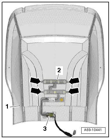
- Carefully detach the passenger occupant detection system sensor -2- with circuit board -3- from the seat cushion -1-.
Installing
 WARNING
- Follow all safety precautions when working with pyrotechnic components. Refer to → Chapter "Pyrotechnic Components Safety Precautions".
- Before handling pyrotechnic components (for example, connecting the connector), the person handling it must "discharge static electricity". This can be done by touching the door striker, for example.
- Position the circuit board -3- for the passenger occupant detection system sensor -2- in the opening -1- in the seat cushion.
- Align the passenger occupant detection system sensor according to the marks -arrows- on the seat cushion.
 Caution
The new passenger occupant detection sensor should be installed in the same location on the seat padding as the old sensor.
- Remove the protective film and adhere the passenger occupant detection system sensor to the seat padding.
Installation is performed in reverse order of removal, while noting the following:
 Note
Note
- Make sure the passenger occupant detection system is not covered by the seat heater element heating coils.
- Make sure the connectors are installed correctly and are secure.
 WARNING
Ignition must be on when connecting battery. If pyrotechnic components (for example, airbag, belt tensioner) are not repaired correctly, they may deploy unintentionally after connecting battery. There must not be anyone inside the vehicle when connecting the battery.
- Connect the battery ground cable with the ignition turned on. Refer to → Electrical Equipment; Rep. Gr.27; Battery; Battery, Disconnecting and Connecting.
 Note
Note
If the Airbag Indicator Lamp -K75- signals a fault after installing, check the DTC memory, erase it and check it again. Refer to Vehicle Diagnostic Tester.
READ NEXT:
 Passenger Occupant Detection System
Component Location Overview - Passenger Occupant Detection System
WARNING
The replacement part (service kit) for the passenger
occupant detection system is already precalibrated and must
Deformation Element
Overview - Deformation Element
1 - Nut
25 Nm
Quantity: 3
2 - Lower Deformation Element
Component location: under the instrument panel on the driver side
RemoSEE MORE:
Options and settings
Options
Context-dependent functions and settings may
be available depending on vehicle equipment, the
selected source, the connected mobile device,
and the connection type.
Requirement: the playback view must be displayed
1 fig. 141.
Press More 11.
Play more like this
The track currently playin
Overview - Center Console
Overview - Center Console, Basic Equipment Level
1 - Storage Compartment
Vehicles with:
With External Audio Source Connection -R199-
Removing and installing. Refer to
→ Chapter "Front Center Console Storage Compartment, Removing and
Installing".
Insert in the mas