Audi Q3: General Information
Suspension
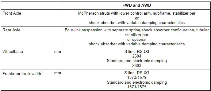
1: Front/rear track width, applies only to 215/65/R16 standard tires on 6.5Jx16 ET33 rims.
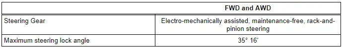
Steering
Tire Types
General information on wheel/tire combinations, winter tires, snow chain, recommended tire manufacturers: → Wheels and Tire;
Tire Pressure Monitoring System General Information
Refer to the Owner's Manual.
If the vehicle has a tire pressure monitoring system display, it will be documented on the vehicle data label or in ELSA in Vehicle-Specific Information under "Vehicle Data" by the PR number. Refer to → Chapter "Explanations of Production Control Numbers (PR Number)".
With the help of the ABS speed sensor, the tire pressure monitoring system compares both the rolling circumference and the vibration behavior of the individual wheels. The instrument cluster display shows if there are any changes to one or more wheels. If only one wheel is affected, the location of the wheel will be indicated.
The tire pressure monitoring system is a software module in the ESP/ABS control module for detecting slow losses of pressure at a wheel location. With the help of the ABS speed sensors, the TPMS compares the speed and rolling circumference of the individuals wheels. If the rolling circumference of a wheel changes, the tire pressure monitoring display indicator lamp lights up in the instrument cluster. Rolling circumference of tire may be change if:
- the tire pressure is too low.
- the tire has structural damage.
- the tire or the pressure was changed and the tire pressures were not saved.
- the vehicle is loaded on one side.
- the tires on one axle are loaded more heavily (for example when towing a trailer or driving up and down inclines).
- Snow chains are installed.
- the spare tire is installed.
- one tire per axle was changed (or if the tires were rotated from front to back or the other way around).
- The left and right wheels drive on different surfaces for an extended period of time.
Tire Pressure Monitoring Display Appearing
The tire pressure monitoring display in the instrument cluster informs the driver if the tire pressure is too low or if there is a system malfunction.
System Fault in the TPMS Display (TPMS Display +)
If the indicator lamp blinks for approximately one minute after switching the ignition on and then stays on continuously, there is a system malfunction. "TPMS" is also displayed in the instrument cluster.
A fault in the system is stored in the ABS/ESP control module event memory and is indicated by a flashing yellow TPMS+ lamp in the instrument cluster (1 minute after the ignition is switched on). The tire pressure monitoring system lamp cannot be switched off by pressing the Multimedia System Control Head -E380- button. Proceed as follows if there is a fault stored in the DTC memory:
- Vehicle Diagnosis Tester Connect.
- Select the correct program in "Guided Functions".
- Follow the instructions on the screen.
Perform calibration: (readapt tire pressure)
The tire pressures must be stored in the MMI each time there is a change in the tire pressure or after a tire has been changed. Refer to the Owner's Manual.
Drive Axle General Information
Lightly coat the splines on the outer joint with assembly paste before installing the outer joint into the wheel hub. Refer to the Parts Catalog.
Never allow the drive axle just to hang loose under the vehicle or to bend them at the joints.
The wheel bearing must not be under a load while the drive axle threaded connection on the wheel side is loose.
If the bearings are loaded by the vehicle weight the wheel bearing will be damaged. This reduces the service life of the wheel bearings. Observe the following when doing so:
Procedure for loosening the drive axle threaded connection on the wheel side. Refer to → Chapter "Drive Axle Threaded Connection, Loosening and Tightening".
Tightening the threaded connection between the drive axle and flange shaft:
First diagonally tighten all six bolts to 10 Nm. Then diagonally tighten them again to the tightening specification.
Vehicles without a drive axle must not be moved, otherwise the wheel bearing will be damaged. If the vehicle must be moved, be sure to note the following:
- Install an outer joint in place of the drive axle.
- Tighten the outer joint to 200 Nm.
Safety Precautions
Start/Stop System Safety Precautions
Note the following when working on a vehicle with the Start/Stop System:
 WARNING
There is a risk of injury if the engine starts automatically in vehicles with the Start/Stop System.
- When the Start/Stop System is on (recognizable by a message in the instrument cluster), the engine may start automatically.
- Make sure the Start/Stop System is off whenever working on the vehicle. Turn off the ignition and turn it back on only when necessary.
Subframe Safety Precautions
Note the following whenever working on the subframe:
 Caution
The suspension components could be damaged.
- Do not rest the vehicle on its wheels if the subframe mount, the steering gear or the subframe crossbrace are not installed correctly.
- Do not support the vehicle on the subframe or the subframe crossbrace, for example, by a floor jack or similar device.
Road Test with Testing Equipment Safety Precautions
If testing equipment is needed on road tests, follow the information below:
 WARNING
Distraction and testing equipment that is not secured properly can cause accidents.
The passenger airbag could pose a risk if it deploys in a collision.
- Operating testing equipment while driving is a distraction.
- Testing equipment that is not secured probably increases the risk of injury.
Always secure testers on the rear seat with a strap and have a second person on the rear seat operate them.
READ NEXT:
 Repair Information
Shock Absorber Leaks
Shock absorbers are frequently rejected and exchanged
because of leaks. Examinations on the test stand and on the
vehicle have shown that the replacement of a large number of
Disposal
Front Shock Absorbers, Venting and Emptying
Method A - Venting through Drill Holes
- Secure gas-filled shock absorber vertically in vise, with
piston rod facing down.
WARNING
Wear
SEE MORE:
Overview - Seat Versions
Component Location Overview - Seat Versions
1 - Front Passenger Seat
Standard Seat/Sport Seat (Manual)
Vehicles with:
Seat/backrest heating
Lumbar Support
Standard seat drawer
Sport seat storage compartment
Footwell lamp
Child Seat Anchor
Seat angle adjustment only for
Glossary of tire and loading
terminology
Accessory weight
means the combined weight (in
excess of those standard items
which may be replaced) of automatic
transmission, power steering,
power brakes, power windows,
power seats, radio, and
heater, to the extent that these
items are available as factory-installed
equipment (whether installed
