Audi Q3: Deformation Element
Overview - Deformation Element
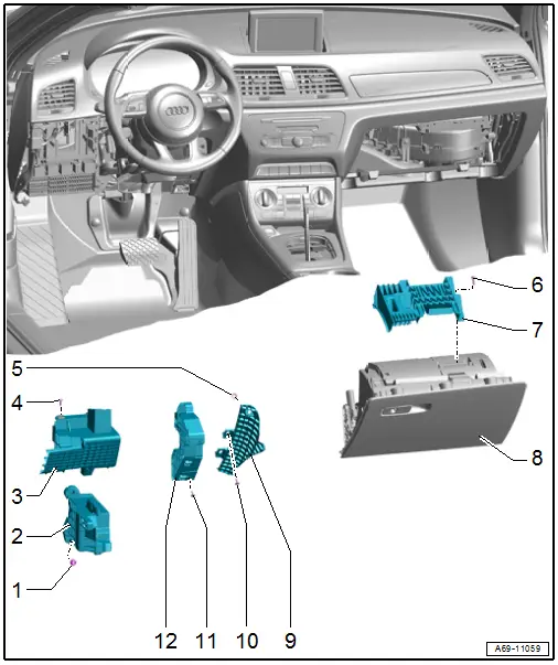
1 - Nut
- 25 Nm
- Quantity: 3
2 - Lower Deformation Element
- Component location: under the instrument panel on the driver side
- Removing and installing. Refer to → Chapter "Lower Deformation Element, Removing and Installing, Driver Side".
3 - Upper Outer Deformation Element
- Component location: under the instrument panel on the driver side
- Removing and installing. Refer to → Chapter "Upper Outer Deformation Element, Removing and Installing, Driver Side".
4 - Bolt
- 3 Nm
- Quantity: 2
5 - Lock Washer
- Replace after removing
- Press on until stop
6 - Bolt
- Quantity: 4
- 1.5 Nm
7 - Front Passenger Side Deformation Element
- Component location: on the glove compartment
- Removing and installing. Refer to → Chapter "Front Passenger Side Deformation Element, Removing and Installing".
8 - Glove Compartment
- Removing and installing. Refer to → Chapter "Glove Compartment, Removing and Installing".
9 - Instrument Panel Deformation Element
- Component location: on the left side of the instrument panel
- Removing and installing. Refer to → Chapter "Instrument Panel Deformation Element, Removing and Installing".
10 - Bolt
- 1.5 Nm
- Quantity: 2
11 - Bolt
- 1.5 Nm
- Quantity: 3
12 - Upper Inner Deformation Element
- Component location: under the instrument panel on the driver side
- Removing and installing. Refer to → Chapter "Upper Inner Deformation Element, Removing and Installing, Driver Side".
Deformation Element, Removing and Installing
Upper Outer Deformation Element, Removing and Installing, Driver Side
Removing
- Remove the instrument panel cover on the driver side. Refer to → Chapter "Driver Side Instrument Panel Cover, Removing and Installing".
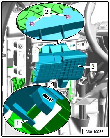
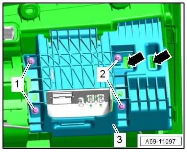
- Remove the bolts -2-.
- Release the hook -1- and remove the deformation element -3- from the relay and fuse carrier toward the rear -arrow-.
Installing
Install in reverse order of removal.
Installation notes, for example tightening specifications, replacing components. Refer to → Chapter "Overview - Deformation Element".
Upper Inner Deformation Element, Removing and Installing, Driver Side
Removing
- Remove the instrument panel cover on the driver side. Refer to → Chapter "Driver Side Instrument Panel Cover, Removing and Installing".
- Remove the lower steering column trim panel. Refer to → Chapter "Lower Steering Column Trim Panel, Removing and Installing".
- Move the steering wheel as far up and backward as possible to be able to use the full steering column adjustment range.
- Unclip the deformation element wire and free it up.
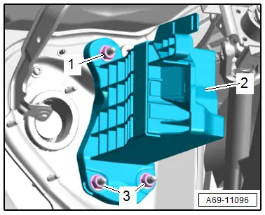
- Remove the bolts -3-.
- Release the hook -1- and remove the deformation element -2- from the instrument panel.
Installing
Install in reverse order of removal.
Installation notes, for example tightening specifications, replacing components. Refer to → Chapter "Overview - Deformation Element".

Lower Deformation Element, Removing and Installing, Driver Side
Removing
- Remove the instrument panel cover on the driver side. Refer to → Chapter "Driver Side Instrument Panel Cover, Removing and Installing".
- Remove the upper outer deformation element. Refer to → Chapter "Upper Outer Deformation Element, Removing and Installing, Driver Side".
- Remove the relay and fuse carrier behind the driver side instrument panel. Refer to → Electrical Equipment; Rep. Gr.97; Relay Panel, Fuse Panel and E-Boxes; Relay and Fuse Carrier behind Driver Side Instrument Panel, Removing and Installing.
- Remove the nuts -1 and 3-.
- Disengage the deformation element -2- at the pins and remove.
Installing
Install in reverse order of removal.
Installation notes, for example tightening specifications, replacing components. Refer to → Chapter "Overview - Deformation Element".
Instrument Panel Deformation Element, Removing and Installing
Removing
- Remove the instrument panel. Refer to → Chapter "Instrument Panel, Removing and Installing".
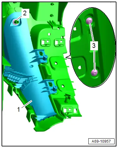
- Remove the bolts -3-.
- Remove the lock washer -2- and remove the deformation element -1- from the instrument panel.
Installing
Install in reverse order of removal.
Installation notes, for example tightening specifications, replacing components. Refer to → Chapter "Overview - Deformation Element".
Front Passenger Side Deformation Element, Removing and Installing
Removing
- Remove the glove compartment. Refer to → Chapter "Glove Compartment, Removing and Installing".
- Remove the bolts -1 and 2-.
- Unclip the deformation element -3- from the glove compartment -arrows- and remove.
Installing
Install in reverse order of removal.
Installation notes, for example tightening specifications, replacing components. Refer to → Chapter "Overview - Deformation Element".
Special Tools
Special tools and workshop equipment required
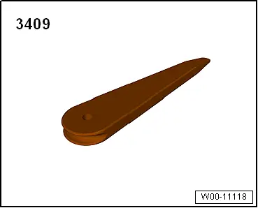
- Trim Removal Wedge -3409-
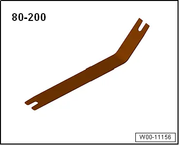
- Pry Lever -80-200-
- TORX screwdriver T25, approximately 100 mm long, commercially available
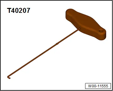
- Hook Tool -T40207-
- Release Tool Set - Extraction Tool 17 -VAS1978/17- from the Release Tool Set -VAS1978/35-
READ NEXT:
 Overview - Front Door Trim Panel
1 - Pull Handle
With switch mount
Removing and installing. Refer to
→ Chapter "Front Pull Handle, Removing and Installing".
2 - Left Front Entry Lamp -W31-
Midrange Speaker Trim, Removing and Installing
Special tools and workshop equipment
required
Wedge Set -T10383-
Removing
- Pry out the speaker trim -1-
along the door trim seam -arrow-
using the Wedge -T10383/1- and remove it.
SEE MORE:
Transmitted information
Data collection
Applies to: vehicles with data collection
Depending on the country, Audi may collect data
for the following purposes, for example: offer
and product optimization, public safety, provision
of Audi connect remote vehicle services, and
adaptation to customer expectations. For example,
v
Front Brake Pads, Removing and Installing
Brake Pads, Removing and Installing, 1LJ, 1ZD Brakes
If old brake pads are being replaced with new ones, then it is necessary
to check the brake rotor thickness for wear. Pay attention to the wear
specifications for the brake rotor.
Special tools and workshop equipment
required
Torque Wr