Audi Q3: Cover and Cushion, Separating
Cover and Cushion, Separating, Bench Seat
Special tools and workshop equipment required
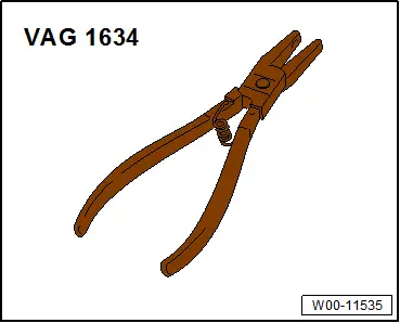
- Upholstery Clip Pliers -VAG1634-
Removing
- Remove the rear bench seat. Refer to → Chapter "Bench Seat/Single Seat, Removing and Installing".
- Remove seat cover with seat cushion for the rear bench seat. Refer to → Chapter "Cover and Cushion, Removing and Installing, Bench Seat".
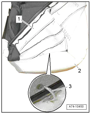
- Remove the seat cover -1- from the seat padding -2- as far as possible and cut the upholstery clips -3- using pliers.
- Remove the seat cover from the seat cushion.
Installing
Install in reverse order of removal.
Installation notes, for example tightening specifications, replacing components. Refer to → Chapter "Overview - Cover and Cushion, Sport Bench Seat".
Cover and Cushion, Separating, Backrest
Special tools and workshop equipment required
- Upholstery Clip Pliers -VAG1634-
Removing
- Remove the rear seat backrest. Refer to → Chapter "Rear Seat Backrest, Removing and Installing".
- Remove the backrest cover and backrest cushion from the rear seat backrest. Refer to → Chapter "Cover and Cushion, Removing and Installing, Backrest".
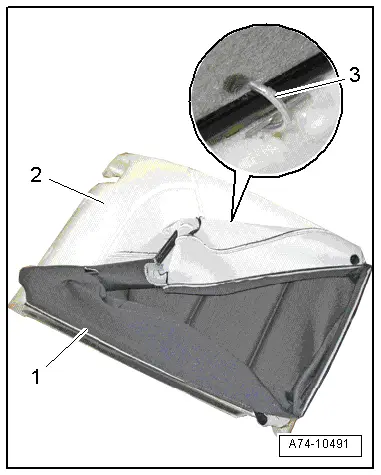
- Remove the backrest cover -1- from the backrest padding -2- as far as possible and cut the upholstery clips -3- using pliers.
Installing
Install in reverse order of removal.
Installation notes, for example tightening specifications, replacing components. Refer to → Chapter "Overview - Cover and Cushion, Backrest without a Pass-Through".
Special Tools
Special tools and workshop equipment required
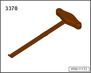
- Backrest Panel Tool -3370-
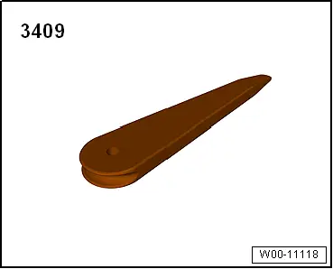
- Trim Removal Wedge -3409-
- Upholstery Clip Pliers -VAG1634-
Edition: A005A001321 - FU - 12/10/2014 - JY1038875
READ NEXT:
 General, Technical data
Identification
Brake PR Numbers
The PR number on the vehicle data label describes which
brake system is installed in the vehicle.
Example of a Vehicle Data Sticker:
A - Front Brakes (eSEE MORE:
Upper Transverse Link, Removing and Installing
Upper Transverse Link, Removing and Installing, FWD Vehicles
Special tools and workshop equipment
required
Torque Wrench 1332 40-200Nm -VAG1332-
Removing
- Measure dimension from center of wheel to lower edge of
wheel housing. Refer to
→ Chapter "Wheel Bearing in Curb Weig
Overview - Steering Column Switch Module
Steering Column Switch Module Assembly Overview, with Mechanical Ignition
Switch
1 - Steering Column
2 - Bolt
Quantity: 2
For steering lock housing (shear bolt)
3 - Lock Cylinder
Removing and installing. Refer to
→ Chapter "Lock Cylinder, Rem