Audi Q3: Airbag Control Module
Overview - Airbag Control Module
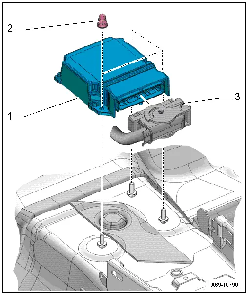
1 - Airbag Control Module -J234-
- Removing and installing. Refer to → Chapter "Airbag Control Module -J234-, Removing and Installing".
- Control module is grounded via the housing with the body.
2 - Nut
- 9 Nm
- Quantity: 3
- The thread must be paint and contaminant free, nut and ground bolts serve as ground connection for the control module
3 - Connector
Airbag Control Module -J234-, Removing and Installing
Removing
 WARNING
Follow all safety precautions when working with pyrotechnic components. Refer to → Chapter "Pyrotechnic Components Safety Precautions".
- Disconnect the battery ground cable with the ignition turned on. Refer to → Electrical Equipment; Rep. Gr.27; Battery; Battery, Disconnecting and Connecting.
- Remove the driver and front passenger footwell trim panel. Refer to → Chapter "Front Footwell Center Console Trim Panel, Removing and Installing".
- Remove the driver and front passenger footwell trim panel bracket. Refer to → Chapter "Front Footwell Center Console Trim Panel Bracket, Removing and Installing".
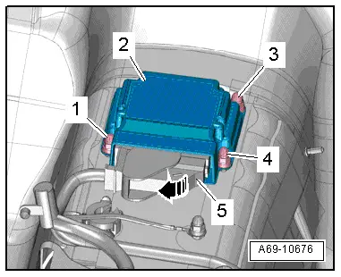
- Remove the front nut in the footwell on the driver side -1-.
 WARNING
Before handling pyrotechnic components (for example, disconnecting the connector), the person handling it must "discharge static electricity". This can be done by touching the door striker, for example.
- Open the securing clip on the connector -arrow- in the front of the footwell on the front passenger side and remove the connector -5-.
- Remove the nuts -3 and 4-.
- Carefully lift the airbag control module -2- from the threaded pins and remove to the passenger side.
Installing
 WARNING
- Follow all safety precautions when working with pyrotechnic components. Refer to → Chapter "Pyrotechnic Components Safety Precautions".
- Before handling pyrotechnic components (for example, connecting the connector), the person handling it must "discharge static electricity". This can be done by touching the door striker, for example.
Install in reverse order of removal. Note the following:
 Note
Note
Make sure the connectors are installed correctly and are secure.
 WARNING
Ignition must be on when connecting battery. If pyrotechnic components (for example, airbag, belt tensioner) are not repaired correctly, they may deploy unintentionally after connecting battery. There must not be anyone inside the vehicle when connecting the battery.
- Connect the battery ground cable with the ignition turned on. Refer to → Electrical Equipment; Rep. Gr.27; Battery; Battery, Disconnecting and Connecting.
 Note
Note
- If the Airbag Indicator Lamp -K75- signals a fault after installing, check the DTC memory, erase it and check it again. Refer to → Vehicle diagnostic tester.
- Code the airbag control module -J234- after replacing it. Refer to → Vehicle diagnostic tester.
- The airbag control module -J234- ground connection is achieved via the housing with the body.
Installation notes, for example tightening specifications, replacing components. Refer to → Chapter "Overview - Airbag Control Module".
READ NEXT:
 Battery Interrupt Igniter
Overview - Battery Interrupt Igniter
1 - Connector
For the Battery Interrupt Igniter -N253-
Releasing and removing
2 - Nuts
15 Nm
3 - Battery Inte
Driver Side Airbag
Overview - Driver Side Airbag
1 - Locking Bracket
Use a T25 TORX screwdriver, approximately 100 mm long
2 - Steering Column Electronics Control Module -J527-
With Air
Front Passenger Airbag
Overview - Front Passenger Airbag
1 - Front Passenger Airbag
With Front Passenger Airbag Igniter 1 -N131-
WARNING
Follow all safety precautions when working with pyro
SEE MORE:
Connector Housings, Releasing and Disassembling
Information on Releasing and Disassembling Connector Housings
Note
Observe general notes for repairs on the vehicle electrical
system. Refer to
→ Chapter "Vehicle Electrical System, General Repair
Information".
Always use the release tools intended for the releasing
pr
Battery
Battery general information
Because of the complex power supply, all work
on batteries such as disconnecting, replacing,
etc., should only be performed by an authorized
Audi dealer or authorized Audi Service Facility.
Multiple batteries with different technologies
may be installed in your vehicle:
