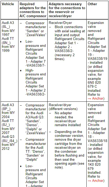
Audi Q3: Adapter for Assembling Flushing Circuit
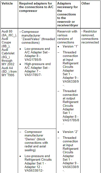
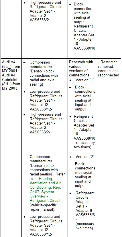
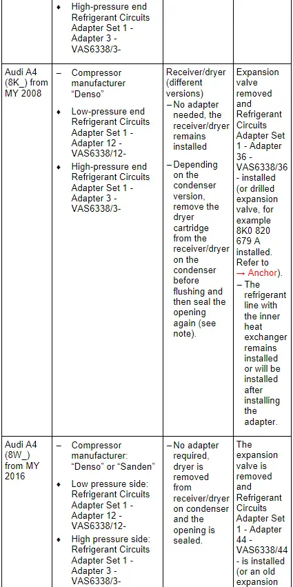
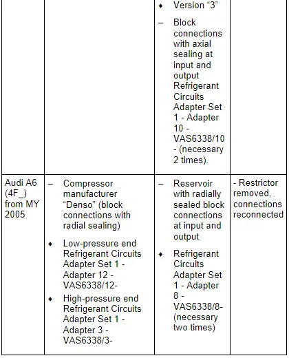
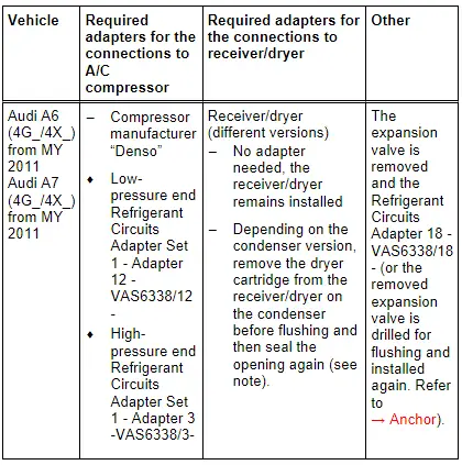
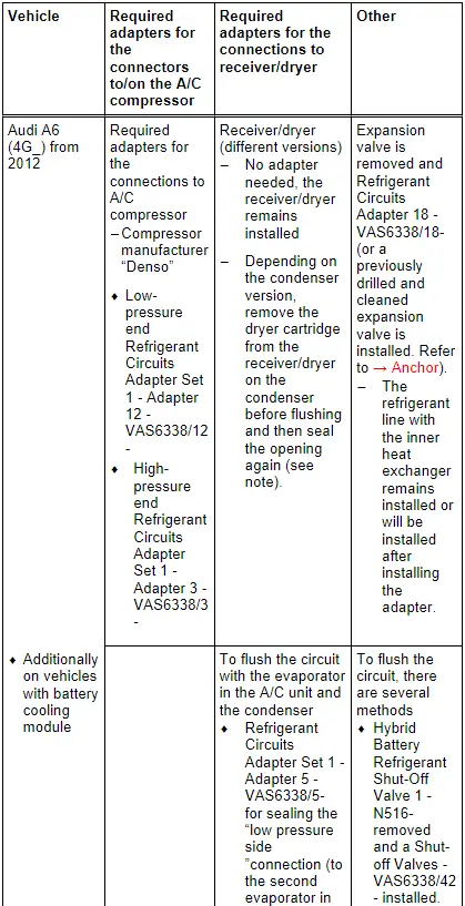
- Various adapters which are required to connect the Air Conditioning (A/C) service station to the refrigerant circuit for flushing and to bridge the removed receiver/dryer or reservoir and expansion valve (specific to vehicle) are in the following table.
- Using a charge hose with 5/8 -18 UNF connections (short version, for example Refrigerant Circuits Adapter Set 1 - Adapter 31 -VAS6338/31-), connect the two adapters (contained in Refrigerant Circuits Adapter Set 1 -VAS6338/1-) which have been installed for the removed reservoir or receiver/dryer.
- If a flushed refrigerant circuit is not reassembled immediately after flushing, adapters remain at connections and seal the connections at the adapters using Refrigerant Circuits Adapter Set 1 - Adapter 30 -VAS6338/30- (from Refrigerant Circuits Adapter Set 1 -VAS6338/1-).
- Depending on the version of the compressor and time period of production, different connection and sealing techniques can be found for the refrigerant circuit. Refer to → Heating, Ventilation and Air Conditioning; Rep. Gr.87; System Overview - Refrigerant Circuit (vehicle-specific repair manual).
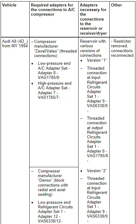
- Beginning from production year 2006, the name of the "Zexel" A/C compressor was changed from "Zexel" to "Valeo".
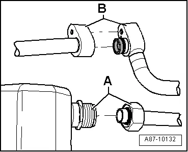
Block or screw connections
- Screw connection -A-
- Block connection -B-
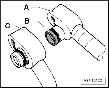
Block connections with different types of seals
- Block connection with radially sealed connection -A- (with plastic or metal guide -B-)
- Block connection with axial sealing connection -C-
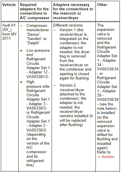
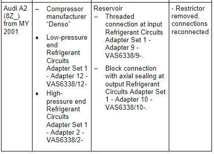
Audi A1 and Audi A2
 Note
Note
- The receiver/dryer may be attached to or integrated in the condenser on the Audi A1/S1, depending on the version of the condenser. A dryer cartridge is installed in the integrated receiver/dryer and can be replaced separately. After flushing, the attached receiver/dryer (introduction still open) must be replaced after the flushing. Refer to the Parts Catalog and → Heating, Ventilation and Air Conditioning; Rep. Gr.87; System Overview - Refrigerant Circuit (vehicle-specific repair manual).
- There are different versions of the A/C unit (different heater core and sears different expansion valve etc.) depending on time period of production and from the VIN number on Audi A1/S1. Refer to the Parts Catalog. For vehicles with the type key "8X1" and "8XA" in the VIN number an expansion valve is installed, on those where both refrigerant lines are attached above, here the Refrigerant Circuits Adapter Set 1 - Adapter 34 -VAS6338/34- fits. For vehicles with the type key "8XF" and "8XK" in the VIN number an expansion valve is installed, on those where both refrigerant lines are attached below, here the Refrigerant Circuits Adapter Set 1 - Adapter 39 -VAS6338/39- fits. Refer to → Heating, Ventilation and Air Conditioning; Rep. Gr.87; Refrigerant Circuit; Expansion Valve, Removing and Installing (vehicle-specific repair manual).
Audi A3, Audi Q3 and Audi TT

 Note
Note
- The version of the receiver/dryer on the Audi A3, Audi Q3 and Audi TT will differ depending on the manufacturer of the condenser. An Audi TT (8J_) from MY 2007 with a 5-cylinder engine has a different condenser version than on models with a 4- or 6-cylinder engine. The receiver/dryer is, for example, inside the condenser. The integrated receiver/dryer has a dryer cartridge that is no longer available as a replacement part. If there are complaints, then it is necessary to replace the complete condenser. Refer to the Parts Catalog and → Heating, Ventilation and Air Conditioning; Rep. Gr.87; System Overview - Refrigerant Circuit (vehicle-specific repair manual).
- If the receiver/dryer or dryer cartridge is integrated in the condenser, then it cannot be replaced separately or is not available as a single part, and the condenser must be replaced. Refer to → Heating, Ventilation and Air Conditioning; Rep. Gr.87; System Overview - Refrigerant Circuit (vehicle-specific repair manual) and the Parts Catalog.
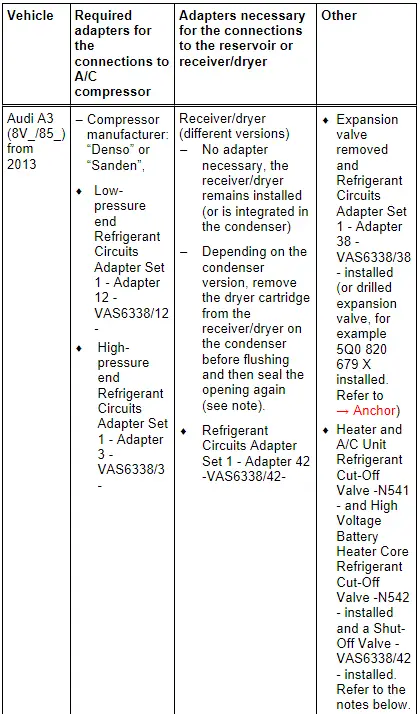
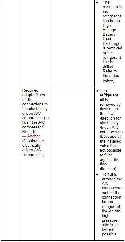
Audi A3 e-tron
 Note
Note
- On the Audi A3 e-tron the refrigerant circuit is flushed in two sections. In the first flushing cycle, the adapter, which is installed for the Heater and A/C Unit Refrigerant Cut-Off Valve -N541-, is opened and the adapter, which is installed for the High Voltage Battery Heater Core Refrigerant Cut-Off Valve -N542- is closed. Thus the refrigerant circuit with the evaporator in the A/C unit is flushed. In the second flushing cycle, the adapter, which is installed for the Heater and A/C Unit Refrigerant Cut-Off Valve -N541-, is closed and the adapter, which is installed for the High Voltage Battery Heater Core Refrigerant Cut-Off Valve -N542- is opened. From this the refrigerant circuit with the evaporator in the high voltage battery heat exchanger is flushed. Refer to → Heating, Ventilation and Air Conditioning; Rep. Gr.87; System Overview - Refrigerant Circuit (vehicle-specific repair manual).
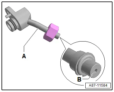
- This illustration shows a refrigerant line -A- with a permanently installed restrictor -B- (without a strainer) This refrigerant line is drilled with a suitable drill 5.0 mm to flush the refrigerant circuit (an inserted restrictor is removed) and cleaned in the flushing circuit before installing. The drilled refrigerant line is replaced after flushing. Refer to the Parts Catalog.
- The diameter of the illustrated variable orifice -B- is approximately 0.7 mm. Depending on the version of the refrigerant line this constriction is either installed fixed in the refrigerant line or only inserted. For the inserted version a strainer for flowing deposits may be installed, which can be blocked by the variable orifice.
- The version of the receiver/dryer on the Audi A3 will differ depending on the manufacturer of the condenser. The receiver/dryer is, for example, inside the condenser. The integrated receiver/dryer has a dryer cartridge that is no longer available as a replacement part. If there are complaints, then it is necessary to replace the complete condenser. Refer to the Parts Catalog and → Heating, Ventilation and Air Conditioning; Rep. Gr.87; System Overview - Refrigerant Circuit (vehicle-specific repair manual).
- If the receiver/dryer or dryer cartridge is integrated in the condenser, then it cannot be replaced separately or is not available as a single part, and the condenser must be replaced. Refer to → Heating, Ventilation and Air Conditioning; Rep. Gr.87; System Overview - Refrigerant Circuit (vehicle-specific repair manual) and the Parts Catalog.
Audi 80, Audi 90, Audi Coupe, Audi Cabriolet and Audi A4
 Note
Note
- There are different versions of the receiver/dryer on the Audi A4 (8K_) from MY 2008, depending on the condenser manufacturer. Refer to → Heating, Ventilation and Air Conditioning; Rep. Gr.87; System Overview - Refrigerant Circuit (vehicle-specific repair manual). The receiver/dryer may be attached to or integrated in the condenser, depending on the version of the condenser. The integrated receiver/dryer has a dryer cartridge that is no longer available as a replacement part. In the event there is a complaint on a vehicle with this condenser, the condenser must be completely replaced. Refer to the Parts Catalog.
- If the receiver/dryer or dryer cartridge is integrated in the condenser, then it cannot be replaced separately or is not available as a single part, and the condenser must be replaced. Refer to → Heating, Ventilation and Air Conditioning; Rep. Gr.87; System Overview - Refrigerant Circuit (vehicle-specific repair manual) and the Parts Catalog.
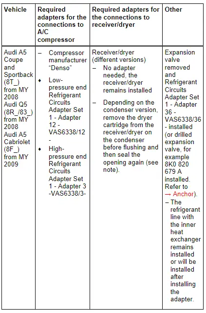
Audi A5 Coupe and Sportback, Audi Q5, Audi A5 Cabriolet
 Note
Note
- There are different versions of the receiver/dryer on this vehicle, depending on the condenser manufacturer. Refer to → Heating, Ventilation and Air Conditioning; Rep. Gr.87; System Overview - Refrigerant Circuit (vehicle-specific repair manual). The receiver/dryer may be attached to or integrated in the condenser, depending on the version of the condenser. The integrated receiver/dryer has a dryer cartridge that is no longer available as a replacement part. In the event there is a complaint on a vehicle with this condenser, the condenser must be completely replaced. Refer to the Parts Catalog.
- If the receiver/dryer or dryer cartridge is integrated in the condenser, then it cannot be replaced separately or is not available as a single part, and the condenser must be replaced. Refer to → Heating, Ventilation and Air Conditioning; Rep. Gr.87; System Overview - Refrigerant Circuit (vehicle-specific repair manual) and the Parts Catalog.
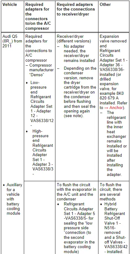
Audi Q5 Hybrid
 Note
Note
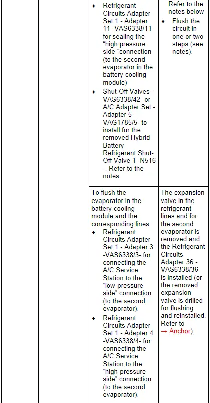
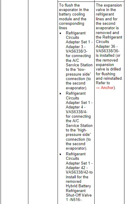
- In vehicles with two evaporators, the refrigerant circuit is flushed in two/three work steps.
- Currently the expansion valves on the evaporator in the A/C unit and on the evaporator in the battery cooling module have the same connections (only the control characteristics and those on the Hybrid Battery Refrigerant Shut-Off Valve 2 -N517- are different).
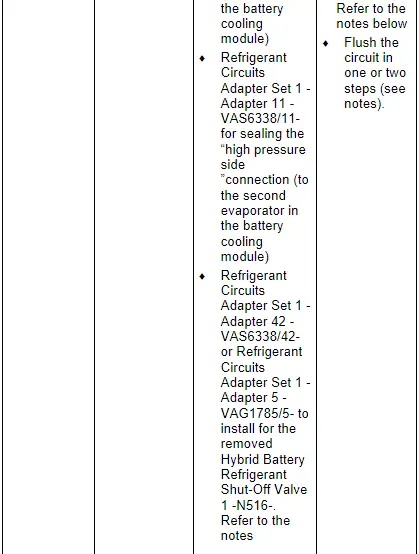
- The refrigerant circuit cannot be rinsed with a Hybrid Battery Refrigerant Shut-Off Valve 1 -N516- installed in the circuit to the evaporator in the A/C unit. The Hybrid Battery Refrigerant Shut-Off Valve 1 -N516- is in a constricted location and prevents the refrigerant from reaching a sufficient flow speed. If a Shut-Off Valve -VAS6338/42- is available, install it for the Hybrid Battery Refrigerant Shut-Off Valve 1 -N516- and open. If the Shut-Off Valves -VAS6338/42- are not available, but there are two A/C Adapter Set - Adapters 5 -VAG1785/5- the circuit with the evaporator in the A/C unit can be rinsed in one work procedure (reassemble the circuit with a filler hose and two A/C Adapter Set - Adapters 5 -VAG1785/5-). If the Shut-Off Valves -VAS6338/42- is not available and there is only one A/C Adapter Set - Adapters 5 -VAG1785/5- available, the circuit must be flushed in two steps. From the low pressure connection on the A/C compressor via the evaporator in the A/C unit up to the connection for the removed Hybrid Battery Refrigerant Shut-Off Valve 1 -N516- and from the connection for the removed Hybrid Battery Refrigerant Shut-Off Valve 1 -N516- via the condenser to the high pressure connection on the A/C compressor.
- There are different versions of the receiver/dryer on this vehicle, depending on the condenser manufacturer. Refer to → Heating, Ventilation and Air Conditioning; Rep. Gr.87; System Overview - Refrigerant Circuit (vehicle-specific repair manual). The receiver/dryer may be attached to or integrated in the condenser, depending on the version of the condenser. The integrated receiver/dryer has a dryer cartridge that is no longer available as a replacement part. In the event there is a complaint on a vehicle with this condenser, the condenser must be completely replaced. Refer to the Parts Catalog.
- If the receiver/dryer or dryer cartridge is integrated in the condenser, then it cannot be replaced separately or is not available as a single part, and the condenser must be replaced. Refer to → Heating, Ventilation and Air Conditioning; Rep. Gr.87; System Overview - Refrigerant Circuit (vehicle-specific repair manual) and the Parts Catalog.
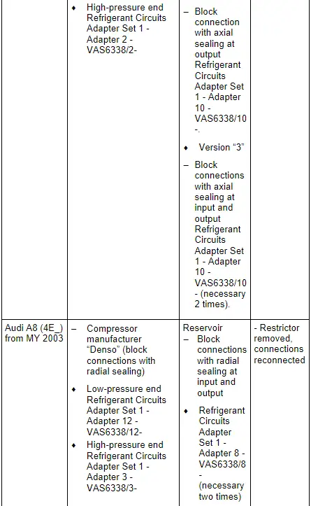
Audi 100, Audi A6 (4A_, 4B_ and 4F_), Audi allroad and Audi V8
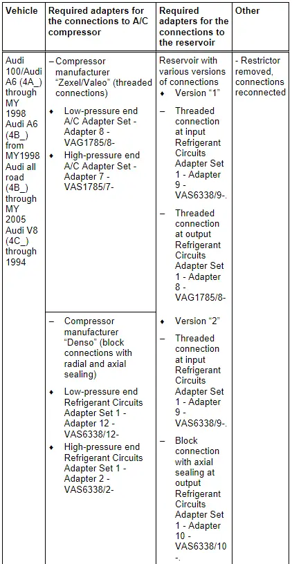
 Note
Note
The specifications for the Audi A6 (4F_) from MY 2005 also apply to the Audi S6 and Audi RS 6.
Audi A6 (4G_ or 4X_ for China), Audi A7 (4G_ or 4X_ for China)
 Note
Note
- The type designation 4X_ is used instead of the type designation 4G_ for specific versions in China
- There are different versions of the receiver/dryer on this vehicle, depending on the condenser manufacturer. Refer to → Heating, Ventilation and Air Conditioning; Rep. Gr.87; System Overview - Refrigerant Circuit (vehicle-specific repair manual) and the Parts Catalog.
- If the receiver/dryer or dryer cartridge is integrated in the condenser, then it cannot be replaced separately or is not available as a single part, and the condenser must be replaced. Refer to → Heating, Ventilation and Air Conditioning; Rep. Gr.87; System Overview - Refrigerant Circuit (vehicle-specific repair manual) and the Parts Catalog.
Audi A6 Hybrid
 Note
Note
- The type designation 4X_ is used instead of the type designation 4G_ for specific versions in China
- In vehicles with two evaporators, the refrigerant circuit is flushed in two/three work steps.
- Currently the expansion valve on the evaporator in the A/C unit and on the evaporator in the battery cooling module have the same connections (only the control characteristics and those on the Hybrid Battery Refrigerant Shut-Off Valve 2 -N517- are different).
- The refrigerant circuit cannot be rinsed with a Hybrid Battery Refrigerant Shut-Off Valve 1 -N516- installed in the circuit to the evaporator in the A/C unit. The Hybrid Battery Refrigerant Shut-Off Valve 1 -N516- is in a constricted location and prevents the refrigerant from reaching a sufficient flow speed. If a Shut-Off Valve -VAS6338/42- is available, install it for the Hybrid Battery Refrigerant Shut-Off Valve 1 -N516- and open. If the Shut-Off Valves -VAS6338/42- are not available, but there are two A/C Adapter Set - Adapters 5 -VAG1785/5- the circuit with the evaporator in the A/C unit can be rinsed in one work procedure (reassemble the circuit with a filler hose and two A/C Adapter Set - Adapters 5 -VAG1785/5-). If the Shut-Off Valves -VAS6338/42- is not available and there is only one A/C Adapter Set - Adapters 5 -VAG1785/5- available, the circuit must be flushed in two steps. From the low pressure connection on the A/C compressor via the evaporator in the A/C unit up to the connection for the removed Hybrid Battery Refrigerant Shut-Off Valve 1 -N516- and from the connection for the removed Hybrid Battery Refrigerant Shut-Off Valve 1 -N516- via the condenser to the high pressure connection on the A/C compressor.
- There are different versions of the receiver/dryer on this vehicle, depending on the condenser manufacturer. Refer to → Heating, Ventilation and Air Conditioning; Rep. Gr.87; System Overview - Refrigerant Circuit (vehicle-specific repair manual). The receiver/dryer may be attached to or integrated in the condenser, depending on the version of the condenser. The integrated receiver/dryer has a dryer cartridge that is no longer available as a replacement part. In the event there is a complaint on a vehicle with this condenser, the condenser must be completely replaced. Refer to the Parts Catalog.
- If the receiver/dryer or dryer cartridge is integrated in the condenser, then it cannot be replaced separately or is not available as a single part, and the condenser must be replaced. Refer to → Heating, Ventilation and Air Conditioning; Rep. Gr.87; System Overview - Refrigerant Circuit (vehicle-specific repair manual) and the Parts Catalog.
- On the Audi A6 hybrid it can be helpful to remove both refrigerant lines in the engine compartment from the inner heat exchanger to flush the components in the battery cooling module and the related refrigerant lines. Then the necessary adapter and related refrigerant hoses can be installed and remove more easily. Refer to → Heating, Ventilation and Air Conditioning; Rep. Gr.87; Refrigerant Circuit; System Overview - Refrigerant Circuit.
- If on the Audi A6 hybrid the knurled nut of the filler hose on the refrigerant line to the evaporator in the battery cooling module installed Refrigerant Circuits Adapter Set 1 - Adapter 3 -VAS6338/3- cannot be installed on the connection (depending of the tolerance on the separation of the refrigerant pipe on the connection) the refrigerant pipe can be carefully bent approximately 1 mm to the side.
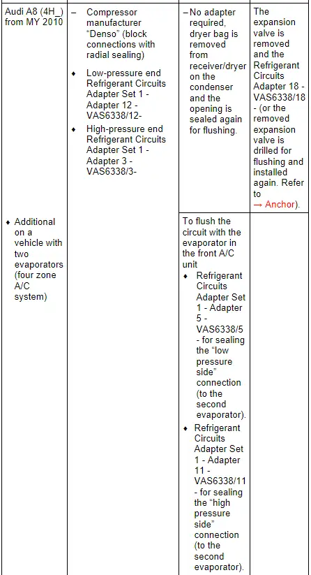
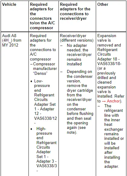
Audi A8
 Note
Note
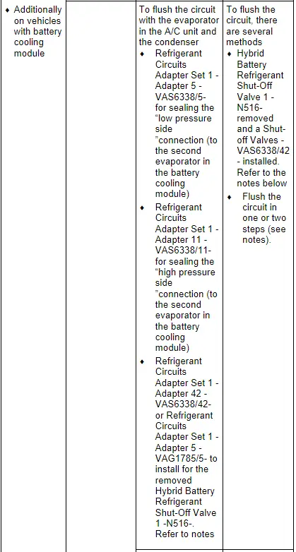
- In vehicles with two evaporators, the refrigerant circuit is flushed in two work steps.
- Currently the front and rear expansion valves have the same connections (only the control characteristics are different)
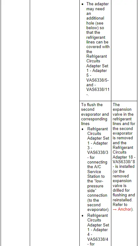
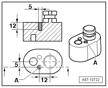
Drill an additional hole in the Refrigerant Circuits Adapter Set 1 - Adapter 5 -VAS6338/5- and -VAS6338/11-.
- Drill a hole -A- in addition to the already existing hole (the dimensions in the illustration are given in mm).
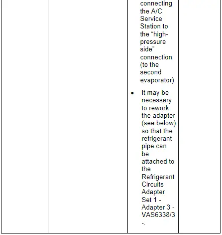
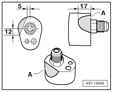
Rework the Refrigerant Circuits Adapter Set 1 - Adapter 3 -VAS6338/3-
- Sand off or file off the Refrigerant Circuits Adapter Set 1 - Adapter 3 -VAS6338/3- near -A- without bending the refrigerant pipe (dimensions are in mm).
Audi A8 Hybrid
 Note
Note
- In vehicles with two evaporators, the refrigerant circuit is flushed in two/three work steps.
- Currently the expansion valve on the evaporator in the A/C unit and on the evaporator in the battery cooling module do not have the same connections.
- The refrigerant circuit cannot be rinsed with a Hybrid Battery Refrigerant Shut-Off Valve 1 -N516- installed in the circuit to the evaporator in the A/C unit. The Hybrid Battery Refrigerant Shut-Off Valve 1 -N516- is in a constricted location and prevents the refrigerant from reaching a sufficient flow speed. If a Shut-Off Valve -VAS6338/42- is available, install and open it for the Hybrid Battery Refrigerant Shut-Off Valve 1 -N516-. If the Shut-Off Valve -VAS6338/42- is not available, but there are two A/C Adapter Set - Adapters 5 -VAG1785/5- and the circuit with the evaporator in the A/C unit can be rinsed in one work procedure (reassemble the circuit with a filler hose and two A/C Adapter Set - Adapters 5 -VAG1785/5-). If the Shut-Off Valves -VAS6338/42- is not available and there is only one A/C Adapter Set - Adapters 5 -VAG1785/5- available, the circuit must be flushed in two steps. From the low pressure connection on the A/C compressor via the evaporator in the A/C unit up to the connection for the removed Hybrid Battery Refrigerant Shut-Off Valve 1 -N516- and from the connection for the removed Hybrid Battery Refrigerant Shut-Off Valve 1 -N516- via the condenser to the high pressure connection on the A/C compressor.
- There are different versions of the receiver/dryer on this vehicle, depending on the condenser manufacturer. Refer to → Heating, Ventilation and Air Conditioning; Rep. Gr.87; System Overview - Refrigerant Circuit (vehicle-specific repair manual). The receiver/dryer may be attached to or integrated in the condenser, depending on the version of the condenser. The integrated receiver/dryer has a dryer cartridge that is no longer available as a replacement part. In the event there is a complaint on a vehicle with this condenser, the condenser must be completely replaced. Refer to the Parts Catalog.
- If the receiver/dryer or dryer cartridge is integrated in the condenser, then it cannot be replaced separately or is not available as a single part, and the condenser must be replaced. Refer to → Heating, Ventilation and Air Conditioning; Rep. Gr.87; System Overview - Refrigerant Circuit (vehicle-specific repair manual) and the Parts Catalog.
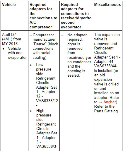
Audi Q7, Audi Q7 e-tron
 Note
Note
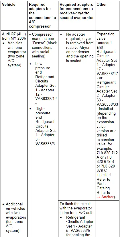
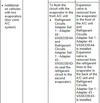
In vehicles with two evaporators, the refrigerant circuit is flushed in two work steps.
 Note
Note
- In vehicles with two evaporators, the refrigerant circuit is flushed in two work steps.
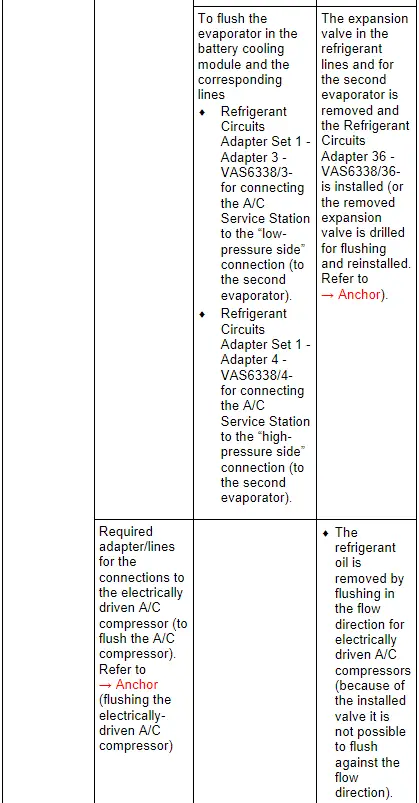
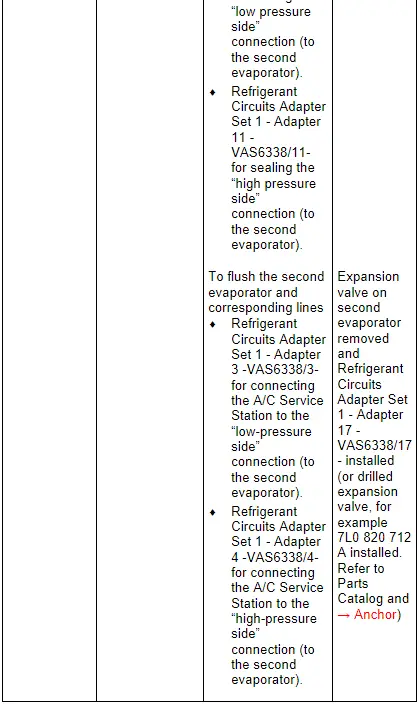
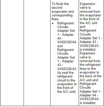
- On vehicles with two evaporators, the refrigerant circuit with the evaporator in the front of the A/C unit is flushed first. So that the refrigerant flows in a fixed direction when flushing, the refrigerant circuit to the second evaporator (in rear of A/C unit) must be blocked off. This is done by removing the expansion valve in the refrigerant lines to the second evaporator and installing the Refrigerant Circuits Adapter Set 1 - Adapter 43 -VAS6338/43- (closed adapter). After the refrigerant circuit with the evaporator is flushed, switch both adapters Refrigerant Circuits Adapter Set 1 - Adapter 43 - VAS6338/43- and Refrigerant Circuits Adapter Set 1 - Adapter 44 - VAS6338/44- and flush the refrigerant circuit with the evaporator in the rear of the A/C unit.
 Note
Note
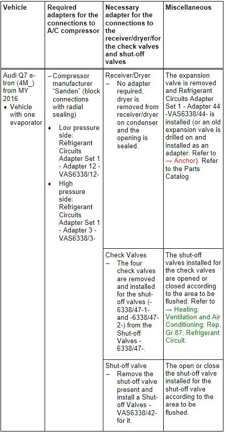
- On the Audi Q7 e-tron the refrigerant circuit is flushed in four steps (flushing circuit). Refer to → Heating, Ventilation and Air Conditioning; Rep. Gr.87; Refrigerant Circuit (Cleaning the A/C system refrigerant circuit).
- So that the entire refrigerant circuit can be flushed, on the Audi Q7 e-tron not only the installed shut-off valve must be positioned correctly (opened or closed). Additionally the electrically activated valves (in the valve block) must be positioned correctly. The activation of the electric valves takes place via different routines which are stored in the respective control module (for example in the Thermal Management Control Module -J1024-). Refer to → Heating, Ventilation and Air Conditioning; Rep. Gr.87; Refrigerant Circuit (Cleaning the A/C system refrigerant circuit).
- To flush on the Audi Q7 e-tron the refrigerant circuit is divided into multiple sections and then cleaned respectively in a flushing cycle. The division takes place by activating the installed electrically activated valves and via the installed manually activated hand shut-off valves. Refer to → Heating, Ventilation and Air Conditioning; Rep. Gr.87; Refrigerant Circuit (Cleaning the A/C system refrigerant circuit) use the Vehicle Diagnostic Tester in the "Guided Fault Finding" function.
- The design of the different flushing circuits for the Q7 e-tron is described in the respective vehicle-specific repair manual. Refer to → Heating, Ventilation and Air Conditioning; Rep. Gr.87; Refrigerant Circuit (Cleaning the A/C system refrigerant circuit).
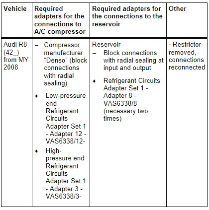
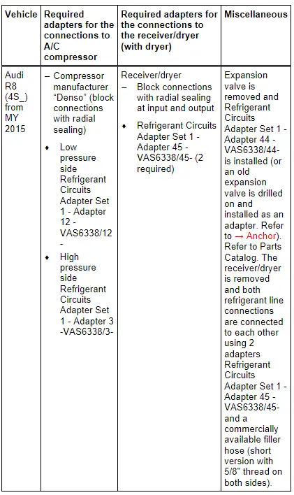
Audi R8
 Note
Note
- The A/C compressor can only be removed when the engine is removed on the Audi R8. The refrigerant lines must be removed in order to be able to flush the refrigerant circuit. Refer to → Heating, Ventilation and Air Conditioning; Rep. Gr.87 ; System Overview - Refrigerant Circuit (vehicle-specific repair manual). With the A/C compressor installed the refrigerant oil quantity in the A/C compressor cannot be emptied, For this reason flushing the refrigerant circuit with the A/C compressor installed would not be productive.
- Both installed condensers are flushed in opposite direction of the refrigerant flow direction.
 Note
Note
- Depending on the engine, the A/C compressor can only be removed when the engine is removed on the Audi R8. The refrigerant lines must be removed in order to be able to flush the refrigerant circuit. Refer to → Heating, Ventilation and Air Conditioning; Rep. Gr.87 ; System Overview - Refrigerant Circuit (vehicle-specific repair manual). With the A/C compressor installed the refrigerant oil quantity in the A/C compressor cannot be emptied, For this reason flushing the refrigerant circuit with the A/C compressor installed would not be productive.
- Both installed condensers are flushed in opposite direction of the refrigerant flow direction.
- A short version of the filler hose is also included in the Refrigerant Circuits Adapter Set 1 -VAS6338/1-.
- The receiver/dryer could potentially be flushed but it will take too much refrigerant because of its large internal volume; the receiver/dryer would ice-up too much when extracting the refrigerant, the refrigerant would evaporate too slowly and extraction would be prolonged too much.
READ NEXT:
 Refrigerant Circuit, Determining Leaks
General Information
Vehicles with a High Voltage System (Hybrid Vehicles)
Extremely Dangerous Due to High-Voltage
The high-voltage system is under high-voltage. Death or serious
bodily injury by
Refrigerant Circuit, Tracing Leaks Using Electronic Leak Detector
Vehicles with a High Voltage System (Hybrid Vehicles)
Read and follow all of the supplemental warnings for all
work performed on vehicles with the high voltage system. Refer
to
→ Chapter
Refrigerant Circuit Complaints
Possible Refrigerant Circuit Concerns
Test Requirements
Electrical Equipment, vacuum system and air duct
fault-finding has not revealed any faults. Refer to Guided Fault
Finding for the A/C sSEE MORE:
Jump starting
Preparation
You should only perform the steps that follow if
you have the necessary tools and technical expertise.
If the engine does not start because the vehicle
battery is drained, you can jump start your vehicle
using another vehicle. Jump start cables are
needed to do this.
Both vehicle batteri
Door Lock, Removing and Installing
Door Lock, Removing and Installing
Caution
There is a risk of malfunctions.
The door lock must be removed and installed together
with the bracket to prevent over-bending the cable when
disengaging and engaging it.
The cable must be disconnected from/attached to the
lever on the d