Audi Q3: Special Tools
Special tools and workshop equipment required
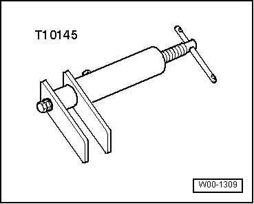
- Piston Resetting Tool -T10145-
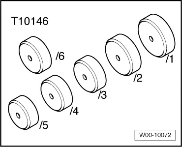
- Piston Resetting Tool - Cap /6 -T10146/6- from Piston Resetting Tool - Caps /1,/2,/3,/4,/5 -T10146-
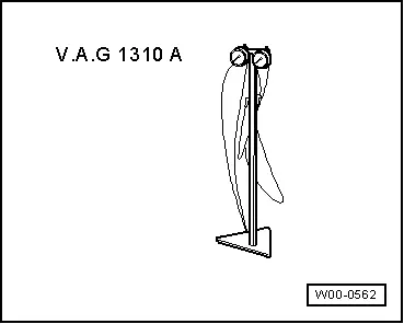
- Brake Pressure Gauge -VAG1310A-
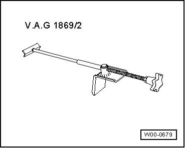
- Brake Pedal Actuator -VAG1869/2-.
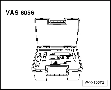
- Brake Line Tool Kit -VAS6056-
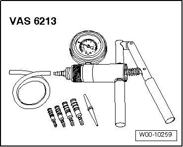
- Hand Vacuum Pump -VAS6213-
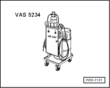
- Brake Charger/Bleeder Unit -VAS5234- with Brake Bleeder Adapter -VAS5234/1-
- Brake Servo Tester -VAS6721-
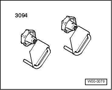
- Hose Clamps - Up To 25mm -3094-
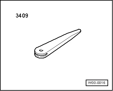
- Trim Removal Wedge -3409-
Listing of individual tools
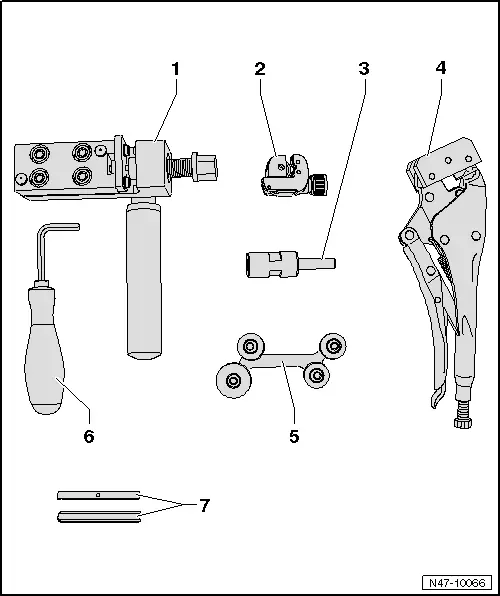
1 - Brake Line Tool Kit - Flanging Tool -VAS6056/1- (including Clamp Jaws -VAS6056/6-)
2 - Brake Line Tool Kit - Pipe Cutter -VAS6056/2-
3 - Brake Line Tool Kit - Brake Line Scraper -VAS6056/3-
- The threaded pins (in shaft and at sides) are set and must not be adjusted!
4 - Brake Line Tool Kit - Line Grips -VAS6056/4-
5 - Brake Line Tool Kit - Pipe Bending Tool - VAS6056/5-
6 - SW6 Angle Screwdriver
7 - Clamp Jaws -VAS 6056/6-, -VAS6056/7-
Flaring Tool (including flaring jaws VAS6056/6)
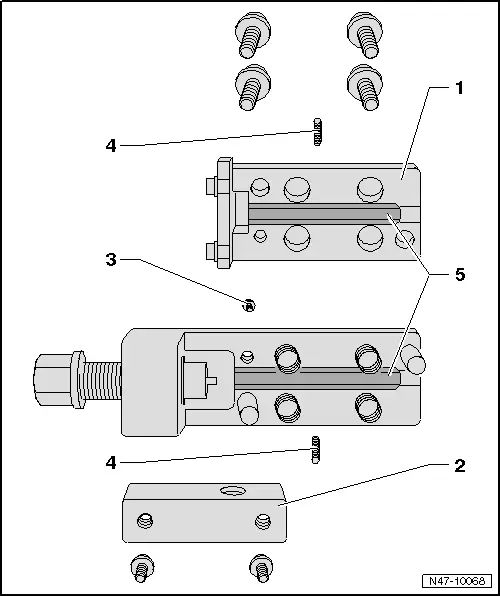
1 - Upper Part of Flaring Tool
- Remove to change Clamp Jaws
2 - Hand Grip Mount
- must be removed to reach the upper section retaining bolt
3 - Screw
- for upper part of flaring tool
4 - Clamp Jaws Threaded Pins
- center and hold the Clamp Jaws
- 2 mm hex socket head
5 - Clamp Jaws
- various
- Assembly instructions, refer to → Fig. "Flaring Jaws Assembly Instructions:"
Edition: A005002421 - LU - 06/17/2015 - TMP.
READ NEXT:
 General Information
Suspension
1: Front/rear track width, applies only to
215/65/R16 standard tires on 6.5Jx16 ET33 rims.
Steering
Tire Types
General information on wheel/tire combinations, winter tires, snow cSEE MORE:
Inner Door Seal, Removing and Installing
Removing
- Remove the rear sill panel strip. Refer to
→ Body Interior; Rep. Gr.70; Passenger Compartment Trim; Sill
Panel Strip, Removing and Installing.
- Remove the upper and lower B-pillar trim. Refer to
→ Body Interior; Rep. Gr.70; Passenger Comp
Center Grille. Removing and Installing, Audi Q3 Offroad
Removing
- Remove the noise insulation. Refer to
→ Chapter "Overview - Noise Insulation".
- Remove the front bumper cover end plate. Refer to
→ Chapter "Front Bumper Cover End Plate, Removing and
Installing".
- Remove the bolts -arrows-.
- Disconnect the co
© 2019-2026 Copyright www.auq3.net | 0.0119
