Audi Q3: Overview - Steering Column Switch Module
Steering Column Switch Module Assembly Overview, with Mechanical Ignition Switch
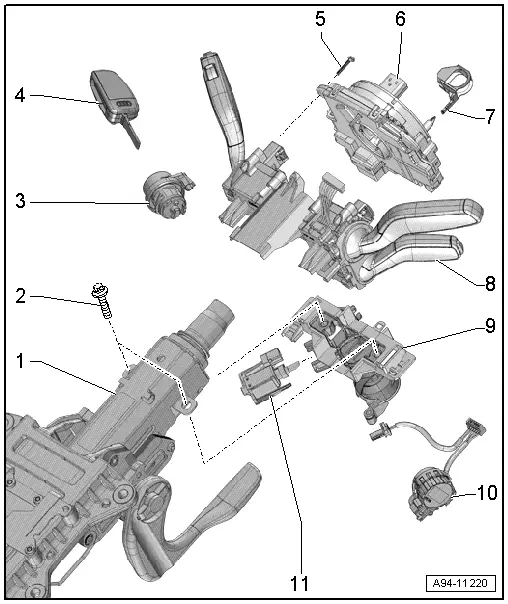
1 - Steering Column
2 - Bolt
- Quantity: 2
- For steering lock housing (shear bolt)
3 - Lock Cylinder
- Removing and installing. Refer to → Chapter "Lock Cylinder, Removing and Installing".
4 - Ignition Key
5 - Bolt
- 1.1 Nm
- Quantity: 3
6 - Steering Column Electronics Control Module -J527-
- With Airbag Spiral Spring/Return Spring with Slip Ring -F138-, Steering Angle Sensor -G85-
- Removing and installing. Refer to → Chapter "Steering Column Electronics Control Module -J527-, Removing and Installing, with Mechanical Ignition Lock".
 Caution
Risk of damaging coil connector.
Coil connector with slip ring is not to be turned following removal.
- Pin assignment for the Steering Column Electronics Control Module -J527-. Refer to → Chapter "Steering Column Electronics Control Module -J527- Connector Assignment, with Mechanical Ignition Lock".
7 - Transport Protection
8 - Mount
- With Turn Signal Switch -E2-, Windshield Wiper Intermittent Mode Switch -E22-
- Vehicle equipment version with cruise control system: with Cruise Control Switch -E45-
- Removing and installing. Refer to → Chapter "Steering Column Combination Switch, Removing and Installing".
9 - Steering Lock Housing
- Removing and installing. Refer to → Chapter "Steering Lock Housing, Removing and Installing".
10 - Ignition/Starter Switch -D-
- Removing and installing. Refer to → Chapter "Ignition/Starter Switch, Removing and Installing".
11 - Ignition Switch Key Lock Solenoid -N376-
- On vehicles with automatic transmission
- Removing and installing. Refer to → Chapter "Ignition Switch Key Lock Solenoid -N376-, Removing and Installing".
Overview - Steering Column Switch Module, with Electronic Ignition Switch
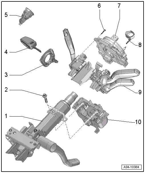
1 - Steering Column
2 - Bolt
- Quantity: 2
- For steering lock housing (shear bolt)
3 - Anti-Theft Immobilizer Reader Coil -D2-
- Removing and installing. Refer to → Chapter "Anti-Theft Immobilizer Reader Coil, Removing and Installing".
4 - Ignition Key
5 - Access/Start Authorization Button -E408-
- Overview. Refer to → Chapter "Component Location Overview - Center Console Controls".
6 - Bolt
- 1.1 Nm
- Quantity: 3
7 - Steering Column Electronics Control Module -J527-
- with Airbag Spiral Spring/Return Spring with Slip Ring -F138-, Steering Angle Sensor -G85-
- Removing and installing. Refer to → Chapter "Steering Column Electronics Control Module -J527-, Removing and Installing, with Electronic Ignition Lock".
 Caution
Risk of damaging coil connector.
Coil connector with slip ring is not to be turned following removal.
- Pin assignment for the Steering Column Electronics Control Module -J527-. Refer to → Chapter "Steering Column Electronics Control Module -J527- Connector Assignment, with Electronic Ignition Lock".
8 - Transport Protection
9 - Mount
- With Turn Signal Switch -E2-, Windshield Wiper Intermittent Mode Switch -E22-
- Vehicle equipment version with cruise control system: with Cruise Control Switch -E45-
- Removing and installing. Refer to → Chapter "Steering Column Combination Switch, Removing and Installing".
10 - Electronic Steering Column Lock Control Module -J764-
- Removing and Installing. Refer to → Suspension, Wheels, Steering; Rep. Gr.48; Steering Column; Electronic Steering Column Lock Control ModuleJ764, Removing and Installing
READ NEXT:
 Lock Cylinder, Removing and Installing
Create an assisting tool from a wire hook as follows:
- Take a 1.5 mm diameter welding wire and bend the end to form
an eye.
- Then cut the welding wire.
Dimension -a- = approximatel
Steering Column Switch Module, Removing and Installing
Steering Column Switch Module, Removing and Installing, with Mechanical
Ignition Lock
Removing
- Adjust steering wheel downward and to rear as far as
possible, use entire adjustment range o
Steering Column Electronics Control Module -J527-, Removing and Installing
Steering Column Electronics Control Module -J527-, Removing and
Installing, with Mechanical Ignition Lock
The Airbag Spiral Spring/Return Spring with Slip Ring -F138-
and the Steering Angle Senso
SEE MORE:
Front Parking Aid Sensor, Removing and Installing
Front Parking Aid Sensors, Removing and Installing, through MY 2014
Right/Left Front Parking Aid Sensor -G252-/-G255-
Special tools and workshop equipment
required
Hook Tool -T40207-
Removing
- Insert the Hook Tool -T40207- in the opening
-1- and remove the lower air intake
grill
Battery in Luggage Compartment, Removing and Installing
Note
If the battery is to be replaced, connect the battery
charger for battery support mode. Refer to
→ Electrical Equipment General Information; Rep. Gr.27; Battery,
Charging.
Removing
- Turn off the ignition.
- Vehicles with ignition lock: Remove the k
