Audi Q3: Drive Axle, Removing and Installing
Removing
- Measure dimension from center of wheel to lower edge of wheel housing. Refer to → Chapter "Wheel Bearing in Curb Weight, Lifting Vehicles with Coil Spring".
- Loosen the drive axle threaded connection. Refer to → Chapter "Drive Axle Threaded Connection, Loosening and Tightening".
- Remove the coil spring. Refer to → Chapter "Spring, Removing and Installing".
- Remove the bolts -lower arrows- on vehicles with a Level Control System Sensor.
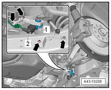
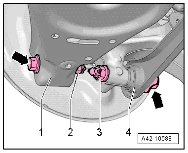
- Remove the bolts -arrows- for the lower control arm -1- and tie rod -4- from the wheel bearing housing.
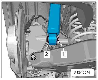
- Remove the bolt -1- and remove it with the washer -2-.
- Loosen the drive axle on the transmission side.
- Pivot the wheel bearing housing outward and remove the drive axle from wheel bearing splines.
- Remove the drive axle.
Installing
Install in reverse order of removal while noting the following:
- Bolting at wheel bearing housing may only occur when the dimension between wheel hub center and lower edge of wheel housing, measured before assembly, is achieved. Refer to → Chapter "Wheel Bearing in Curb Weight, Lifting Vehicles with Coil Spring".
- Lightly coat the splines on the outer joint with assembly paste before installing the outer joint into the wheel hub. Refer to the Parts Catalog.
- Install the coil spring. Refer to → Chapter "Spring, Removing and Installing".
- On vehicles with electronically controlled damping, perform the function "Adapt the control position" with the Vehicle Diagnosis Tester.
- If the control position was reprogrammed and if the vehicle has lane assist, then it will then be necessary to calibrate the driver assistance systems front camera. Refer to → Chapter "Driver Assistance Systems Front Camera, Calibrating".
- On vehicles with level control system sensor, perform headlamp basic setting. Refer to → Electrical Equipment; Rep. Gr.94; Headlamp, Adjusting.
Tightening Specifications
- Drive axle threaded connection to the rear final drive.
READ NEXT:
 Drive Axle, Disassembling and Assembling
Drive Axle, Disassembling and Assembling, Drive Axle with 100 mm Inner CV
Joint
Special tools and workshop equipment
required
Tripod Joint Tool -T10065-
Torque Wrench 1331 5-50Nm -VAG1331-
Drive Axle Threaded Connection, Loosening and Tightening
Special tools and workshop equipment
required
Socket AF 24 mm -T10361A-
Digital Torque Wrench -VAG1756A-
The wheel bearing must not be under a load while the
driveshaft threaded connectio
Special Tools
Special tools and workshop equipment
required
Shock Absorber Set -T10001-
Tensioning Strap -T10038-
Tripod Joint Tool -T10065-
Locating Pins -T10096-
Engine/Gearbox JacSEE MORE:
Vehicle Alignment
Axle Alignment Information
Wheel alignment must only performed using VW/Audi-approved
wheel alignment equipment.
Each time wheels are aligned, both front and rear wheels
must be aligned.
Otherwise, proper vehicle drivability cannot be ensured.
Otherwise centering of toothed shaft cannot be g
Acceptable Tread Depth Variance
Model with Longitudinally Installed Engine
Tread variance for models with a longitudinally installed
engine, such as A4, A5, A6, A7, A8, Q5, Q7, ...
In this case, the variance between the front and rear axle
may not be more than 2 mm
Note
For all four wheels use only tires of the