Audi Q3: Overview - Front Brake Caliper
Overview - Front Brake Caliper, Single-Piston Brake
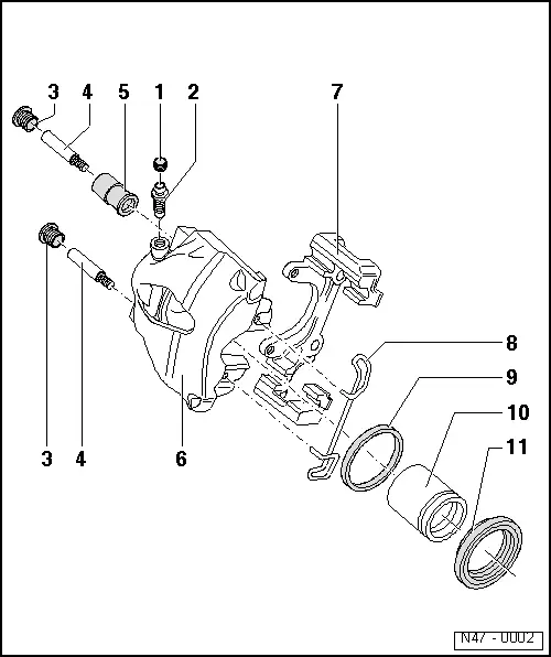
1 - Protective Cap
- Place on the bleed screw
2 - Bleeder Screw
- 10 Nm
- Before installing, lightly coat the thread with Lithium Grease -G 052 150 A2-.
3 - Caps
- Insert in bushing
4 - Guide Pin
- 30 Nm
5 - Bearing Bushing
- Insert in brake caliper
6 - Brake Caliper
7 - Brake Carrier
- Supplied as an assembled replacement part with sufficient grease on guide pins
- If the protective caps are damaged, install repair kit; use included grease packet to grease the guide pins.
8 - Spring
- Insert in both holes of brake caliper
9 - Seal
- Removing and installing, refer to → Chapter "Brake Caliper Piston, Removing and Installing".
- Do not damage when installing piston
10 - Piston
- Removing and installing, refer to → Chapter "Brake Caliper Piston, Removing and Installing".
- Thinly coat the piston with Lithium Grease -G 052 150 A2-
11 - Protective Cap
- Removing and installing, refer to → Chapter "Brake Caliper Piston, Removing and Installing".
- Pull onto piston with outer sealing lip
Overview - Front Brake Caliper, Eight-Piston Brake
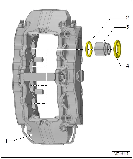
1 - Brake Caliper
2 - Seal
- Quantity: 8
3 - Brake Caliper Piston
- Quantity: 8
- Removing and installing, refer to → Chapter "Brake Caliper Piston, Removing and Installing, Eight-Piston Brake".
4 - Protective Cap
- Quantity: 8
- When damaged, install the complete repair kit, refer to the Parts Catalog.
READ NEXT:
 Brake Caliper Piston, Removing and Installing
Brake Caliper Piston, Removing and Installing, Single-Piston Brake
Special tools and workshop equipment
required
Trim Removal Wedge -3409-
Piston Resetting Tool -T10145-
Piston Resetting To
Rear Brake Caliper
Overview - Rear Brake Caliper
1 - Brake Caliper
Pre-bleed brake caliper after repairing, refer to
→ Chapter "Hydraulic System, Pre-Bleeding".
2 - Bolt
35
Overview - Brake Booster/Master Brake Cylinder
Note
Brake master cylinder and brake boosters can be replaced
independently of one another.
1 - Heat Shield
2 - Nut
25 Nm
Always replace if removed
SelSEE MORE:
Messages
Text messages
Applies to: vehicles with telephone
Requirement: your mobile device must be connected
to the MMI via Bluetooth Message Access
Profile (Bluetooth MAP).
Applies to: MMI: Select on the home screen:
MESSAGES > () > Text message
(telephone
1)/Text message (telephone 2).
The fol
Tire pressure monitoring system
General notes
Each tire, including the spare (if provided),
should be checked monthly when cold and inflated
to the inflation pressure recommended by the
vehicle manufacturer on the vehicle placard or
tire inflation pressure label. (If your vehicle has
tires of a different size than the size indica
© 2019-2026 Copyright www.auq3.net | 0.0094
