Audi Q3: Overview - Bench Seat/Single Seat
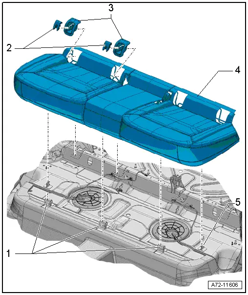
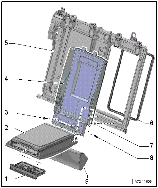
1 - Front Mount
- For securing the rear bench seat
- Welded to the floor panel.
2 - Cover
- For child seat anchor
- Quantity: 4
- Removing and installing. Refer to → Chapter "Child Seat Anchor Guide, Removing and Installing, Rear".
- Must be secure in the anchor
3 - Guide
- For child seat anchor
- Quantity: 4
- Removing and installing. Refer to → Chapter "Child Seat Anchor Guide, Removing and Installing, Rear".
- Must be secure in the anchor
4 - Rear Bench Seat
- Removing and installing. Refer to → Chapter "Bench Seat/Single Seat, Removing and Installing".
- The seat frame must correctly in the mount.
5 - Side Mount
- Quantity: 2
- For securing the rear bench seat
- Welded to the floor panel.
Overview - Locking Mechanism
 Note
Note
The overview shows the locking mechanism on the left 1/3 rear seat backrest. The locking mechanism on the right 2/3 rear seat backrest is identical.
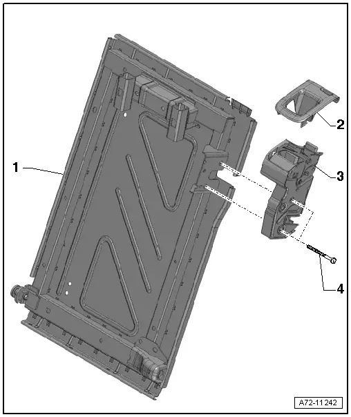
1 - Rear Seat Backrest Frame
2 - Trim
- For locking
- Removing and installing. Refer to → Chapter "Locking Mechanism Trim, Removing and Installing".
- Press on until it engages audibly
3 - Locking Mechanism
- For the rear seat backrest
- Removing and installing. Refer to → Chapter "Rear Seat Backrest Locking Mechanism, Removing and Installing".
4 - Bolt
- 25 Nm
- Quantity: 2
Overview - Headrest and Headrest Guide
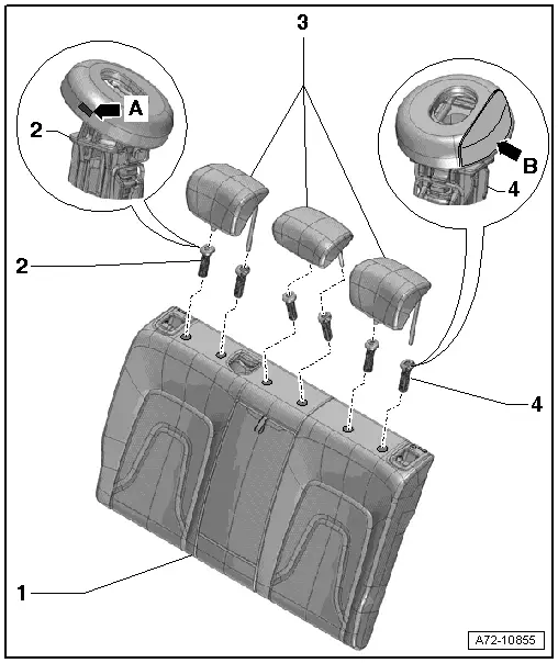
1 - Rear Seat Backrest
2 - Headrest Guide
- With securing spring -arrow A-
- Always installed on the rear seat backrest on the right side
- Removing and installing. Refer to → Chapter "Headrest Guide, Removing and Installing".
- The guide tab must engage in the mount cut-out on the headrest guide
- Push in until the retaining tabs correctly latch to the rear seat backrest frame.
3 - Head Restraint
- Removing and installing. Refer to → Chapter "Headrest, Removing and Installing".
- Must be locked in the headrest guides
4 - Headrest Guide
- With headrest height adjustment button -arrow B-
- Always installed on the rear seat backrest on the left side
- Removing and installing. Refer to → Chapter "Headrest Guide, Removing and Installing".
- The guide tab must engage in the mount cut-out on the headrest guide
- Push in until the retaining tabs correctly latch to the rear seat backrest frame.
Overview - Rear Seat Backrest
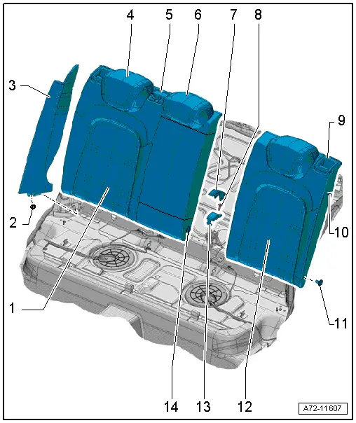
1 - Right 2/3 Rear Seat Backrest
- Removing and installing. Refer to → Chapter "Rear Seat Backrest, Removing and Installing".
2 - Nut
- 9 Nm
- Quantity: 2
3 - Side Padding with Side Airbag
- Equipment levels
- Driver side: with Driver Side Rear Thorax Airbag Igniter -N201-
- Passenger side: with Passenger Side Rear Thorax Airbag Igniter -N202-
 WARNING
Follow all safety precautions when working with pyrotechnic components. Refer to → Chapter "Pyrotechnic Components Safety Precautions".
- Quantity: 2
- Removing and installing. Refer to → Chapter "Rear Side Padding With Side Airbag, Removing and Installing".
- Engage in the seat belt guide at the top first
4 - Outer Headrests
- Quantity: 2
- Removing and installing. Refer to → Chapter "Headrest, Removing and Installing".
5 - Rear Center Belt Guide
- Replace the entire belt guide if damaged.
- Removing and installing. Refer to → Chapter "Rear Seat Belt Guide in Center Seating Position, Removing and Installing".
6 - Headrest in the Center
- Removing and installing. Refer to → Chapter "Headrest, Removing and Installing".
7 - Cover
- For the center bracket
- Removing and installing. Refer to → Chapter "Rear Seat Backrest, Removing and Installing".
- Press on until it engages audibly
8 - Bolt
- 9 Nm
9 - Trim
- For locking
- Quantity: 2
- Removing and installing. Refer to → Chapter "Locking Mechanism Trim, Removing and Installing".
- Press on until it engages audibly
10 - Locking Mechanism
- For the rear seat backrest
- Quantity: 2
- Removing and installing. Refer to → Chapter "Rear Seat Backrest Locking Mechanism, Removing and Installing".
11 - Outer Bearing Sleeve
- Quantity: 2
- Place in the rear seat backrest frame and push until stop.
12 - Left 1/3 Rear Seat Backrest
- Removing and installing. Refer to → Chapter "Rear Seat Backrest, Removing and Installing".
13 - Securing Bracket
- For the center bracket
- Removing and installing. Refer to → Chapter "Rear Seat Backrest, Removing and Installing".
14 - Inner Mounting Pin
- 13.5 Nm
- For the rear seat backrest
- Quantity: 2
- Removing and installing. Refer to → Chapter "Rear Seat Backrest, Removing and Installing".
Overview - Center Armrest
1 - Cupholder
- Removing and installing. Refer to → Chapter "Cupholder, Removing and Installing".
- Install and press on it until it audibly latches
2 - Center Armrest
- Removing and installing. Refer to → Chapter "Center Armrest, Removing and Installing".
3 - Bolt
- 9 Nm
- Quantity: 2
- Secured with lock washer -item 7-.
4 - Door
- For pass-through
- Removing and installing. Refer to → Chapter "Pass-Through Cover, Removing and Installing".
5 - Right 2/3 Rear Seat Backrest
- With pass-through
- Equipment levels
6 - Cover Frame
- For pass-through
- Clipped into the rear seat backrest
- Removing and installing. Refer to → Chapter "Pass-Through Cover Frame, Removing and Installing".
- Press on until it engages audibly
7 - Lock Washer
- For bolt -item 3-
- Quantity: 2
8 - Bolt
- 12 Nm
- Quantity: 4
- Self-locking
- Replace after removing
- Threaded holes for bolts must be cleaned, for example, with a thread tap
9 - Center Cushion
- Removing and installing. Refer to → Chapter "Center Cushion, Removing and Installing".
- Press on until it engages audibly
READ NEXT:
 Bench Seat/Single Seat, Removing and Installing
Removing
- Move the front seats all the way forward.
- Unclip the child seat anchor guides (quantity: four)
-1- from anchorages. Refer to
→ Chapter "Child Seat Anchor Guide, Remov
Rear Seat Backrest, Removing and Installing
Rear Seat Backrest, Removing and Installing
Note
The following describes removing and installing the right
2/3 section of the backrest. Removing and installing the left
1/3 rear seat ba
Locking Mechanism Trim, Removing and Installing
Special tools and workshop equipment
required
Trim Removal Wedge -3409-
Removing
- Unlock the rear seat backrest.
- Make sure the button -2-
(indicator) is in the "up" position.SEE MORE:
Attachments, Removing and Installing
Bumper Cover Side Mount, Removing and Installing
Removing
- Remove the rear bumper cover. Refer to
→ Chapter "Bumper Cover, Removing and Installing".
- Remove the bolts -arrows-.
- Remove the bumper cover mount -1-.
Installing
Install in reverse order of removal. Note t
Vacuum Pump, Removing and Installing
Vacuum Pump, Removing and Installing, Vehicles with 2.0L TFSI Engine
Removing
- Remove the engine cover, refer to
→ Rep. Gr.10; Engine Cover; Engine Cover, Removing and
Installing.
- Remove the air filter housing, refer to
→ Engine Mechanical, Fuel Injection a