Audi Q3: LED Headlamp, Adjusting
Checking and adjusting conditions
- Tire pressure is OK.
- The headlamp glass must be clean and dry.
- The headlamp glass must not be damaged.
- Headlamp reflectors and bulbs are OK.
- The vehicle must be under load.
Vehicle load on driver seat in otherwise unloaded vehicle (curb weight).
- One person or 75 kg.
The curb weight is the weight of the operational vehicle with a completely full fuel tank, including the weight of all equipment carried in operation.
- Fuel tank: at least 90% full.
- Equipment: for example, spare wheel, tools, vehicle jack, fire extinguisher, etc.
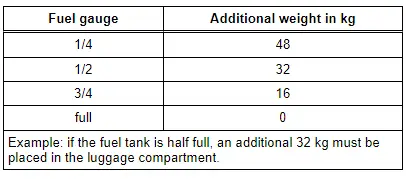
If the fuel tank is not at least 90% full, the load must be created as follows.
- Check fuel tank fill level on the fuel gauge in the instrument cluster and compare with the following table. Place additional weight in the luggage compartment, if necessary.
 Note
Note
Use fuel containers filled with water as additional weight (a five liter fuel container filled with water weighs five kg).
- Roll the vehicle several meters or move it back and forth several times to set the springs.
- The electromechanical parking brake must not be engaged so the vehicle is not under stress.
- The vehicle and headlamp adjusting unit must be on a level surface.
- The headlamp adjusting unit must be aligned to the vehicle. Refer to the Headlamp Adjusting Unit Operating Instructions.
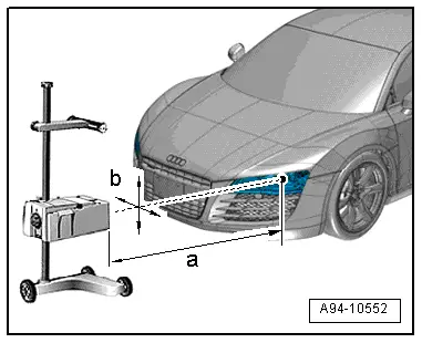
- The headlamp adjusting unit must be distance -a- 30 to 70 cm in front of the headlamp and should not deviate more than dimension -b- = 3 cm from the headlamp center point.
- The angle dimension is set on the headlamp adjusting unit. Refer to the Headlamp Adjusting Unit Operating Instructions.
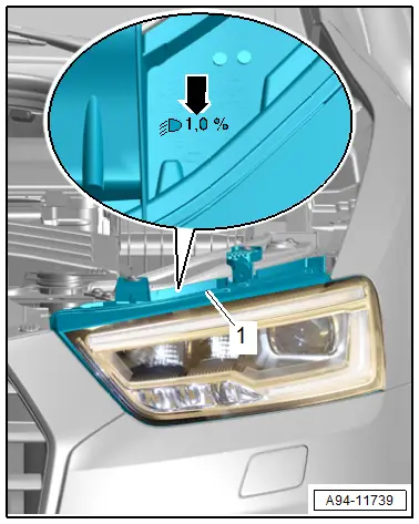
- The angle dimension -arrow- is stamped for ECE countries on the upper edge of headlamp -1- in "%".
- The standard angle dimension for the USA is 0.7%.
 Note
Note
The percentage value is based on a 10 meter projection distance. An angle dimension of 1.0%, for example, converts to 10 cm.
Procedure
- The vehicle must be on a flat surface.
- Turn the headlamp switch to "low beam" - not to "Auto".
- Close all the doors and the rear lid and keep them closed for the duration of the testing/adjusting procedure.
Procedure
- Connect the Vehicle Diagnostic Tester.
- Select the Diagnostic mode and start the diagnostics.
- Select the test plan tab.
- Select the Select individual tests button and choose the following sequence.
- Body
- Electrical Equipment
- 01 - OBD-capable systems
- 09 - Electronic central electric system J519
- 09 - Vehicle Electrical System Control Module, functions
- 09 - adjust LED headlamp (Repair Group 94)
 Note
Note
The headlamps move into the basic setting with this program.
- Follow the instructions in the Vehicle Diagnostic Tester display.
- During the program, you will be asked to perform a headlamp adjustment.
Headlamp adjustment
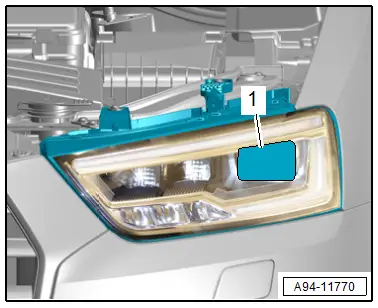
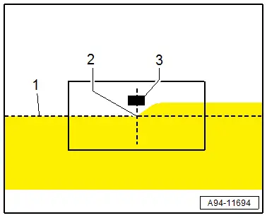
- The headlamp adjusting unit must be aligned at the center of the marked reflector segment -1-.
- The horizontal light-dark border must touch the dividing line -1- on the adjusting unit test surface.
- The bend point -2- between the left horizontal part and the right rising part of the light-dark border must run vertically through the central mark -3-. The bright core of the light beam must be to the right of the vertical.
 Note
Note
- To determine the point -2- more easily, cover and uncover the left half of the headlamp (seen in direction of travel) several times. Then check the low beam again.
- After a correct headlamp adjustment, the center of the high beam light beam must be on the central marking -3-.
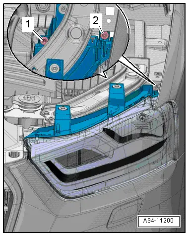
- To adjust the height of the headlamp, set the light-dark border just under the dividing line with the adjustment screw -1-.
- Then adjust the light-dark border on the dividing line starting from the bottom.
- Turn the adjusting screw -2- for side adjustment.
 Note
Note
The allocation on the right headlamp is a mirror image.
- Complete the "basic setting" after the successful headlamp adjustment. Switch off the ignition and disconnect the diagnostic connector.
Auxiliary Headlamps, Adjusting
Retrofitted auxiliary headlamps must be checked and adjusted according to the guidelines used for other systems.
READ NEXT:
 Left/Right Front Turn Signal Bulb -M5- / -M7-, Removing and Installing
Left/Right Front Turn Signal Bulb -M5-/-M7-, Removing and Installing,
Halogen Headlamps
Removing
- Remove the headlamp housing. Refer to
→ Chapter "Headlamp, Removing and Installing,
Left/Right HID Headlamp Bulb -L13-/-L14-, Removing and Installing
Left/Right HID Headlamp Bulb -L13-/-L14-, Removing and Installing,
through MY 2014
WARNING
High voltage poses a life-endangering risk, injury
risk and environmental hazard.
HID headla
Left/Right HID Headlamp Control Module -J343-/-J344-, Removing and
Installing
Left/Right HID Headlamp Control Module -J343-/-J344-, Removing and
Installing, through MY 2014
Removing
- Remove the headlamp housing. Refer to
→ Chapter "Headlamp, Removing and Inst
SEE MORE:
Door, Adjusting
Special tools and workshop equipment
required
Gauge - Gap Adjustment -3371-
Door Adjustment Template -T40038 /16-
Check the height adjustment using the Door Adjustment
Template -T40038 /16-.
- Place the template on top of the trim strip
-1- on side with the marking
-min.- as sho
Overview - Condenser
Overview - Condenser, Dryer Cartridge
Note
There are different versions of the condenser, radiator and
auxiliary radiator. Observe the correct allocation of these components.
Refer to the Parts Catalog.
The "Modine" condenser is shown in the illustration.
1 - Conde
