Audi Q3: High Pressure Sensor -G65-, Removing and Installing
 Note
Note
- When the High Pressure Sensor -G65- is removed, the cooling output cannot be checked. The Climatronic Control Module -J255-/A/C Control Module -J301- control head does not switch on the Air Conditioning (A/C) compressor. Refer to Vehicle Diagnostic Tester in the "Guided Fault Finding" function, A/C system, "Read measured values".
- The refrigerant circuit remains closed, connection with valve.
- Check the function of the High Pressure Sensor -G65- and the signal sent. Refer to Vehicle Diagnostic Tester in "Guided Fault Finding" function and → Chapter "High Pressure Sensor -G65-, Checking Pressure Signal".
- After switching off the A/C compressor in this vehicle, it may take a relatively long time for the pressure on the high pressure side to decrease. This is because the expansion valve is cold and the pressure on the low pressure side increases quickly after shutting the compressor off, then the expansion valve closes and the refrigerant flows slowly to the low pressure side.
 WARNING
Danger due to refrigerant coming out under pressure when there is a defective valve in the refrigerant circuit.
Danger of frost bite to skin and other parts of the body.
- If the refrigerant starts to leak out of the refrigerant line longer than 1 second when loosening the Refrigerant Circuit Pressure Sensor -G805-, retighten the Refrigerant Circuit Pressure Sensor -G805- immediately.
- For the removal and installation of a faulty valve, extract the refrigerant. Refer to → Refrigerant R134a, Servicing; Rep. Gr.87; Refrigerant Circuit (Refrigerant R134a, Servicing; Refrigerant Circuit, Using Service Station).
- Replace the faulty valve in the refrigerant line. Refer to → Refrigerant R134a, Servicing; Rep. Gr.87; A/C System, General Information (Refrigerant R134a, Servicing, A/C System, General Information).
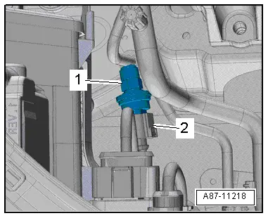
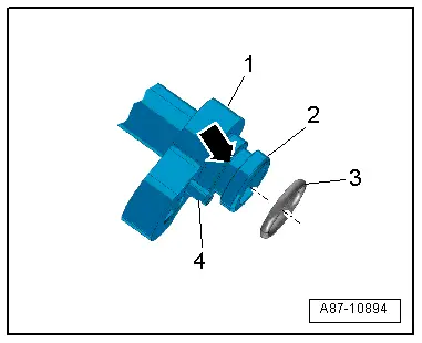
Removing
- Disconnect the connector -2-.
- Remove the High Pressure Sensor -G65- item -1-.
Installing
Installation is done is reverse order, observe the following:
- Replace the O-ring seal. Refer to → Chapter "Refrigerant Circuit Seals". For allocation, refer to the Parts Catalog.
Refrigerant Lines, Disconnecting and Connecting at Expansion Valve
Special tools and workshop equipment required
- Engine Bung Set -VAS6122-
 WARNING
Danger due to refrigerant coming out under pressure.
Danger of frost bite to skin and other parts of the body.
- Extract the refrigerant and immediately open the refrigerant circuit after that.
- If the refrigerant was extracted more than 10 minutes in the past and the refrigerant circuit was not opened, extract the refrigerant again. Pressure in the refrigerant circuit is caused by evaporation.
Removing
- Vehicles with TDI engine, remove the engine cover. Refer to → Rep. Gr.10; Engine Cover, Removing and Installing.
- Discharge the refrigerant circuit. Refer to → Refrigerant R134a, Servicing; Rep. Gr.87; Refrigerant Circuit (Refrigerant R134a, Servicing; Refrigerant Circuit, Using Service Station).
 Note
Note
Depending on engine and vehicle version, it may be necessary to loosen or to remove the following components: upper engine cover, compressed air pipe to throttle valve part and, depending on engine, the intake manifold, etc. Refer to → Engine Mechanical; Rep. Gr.21; Overview - Charge Air System.
Vehicles with 5-Cylinder Engine (Audi RS Q3)
- Remove the air guide pipe (from the air filter to the turbocharger). Refer to → Engine Mechanical; Rep. Gr.21; Overview - Charge Air System.
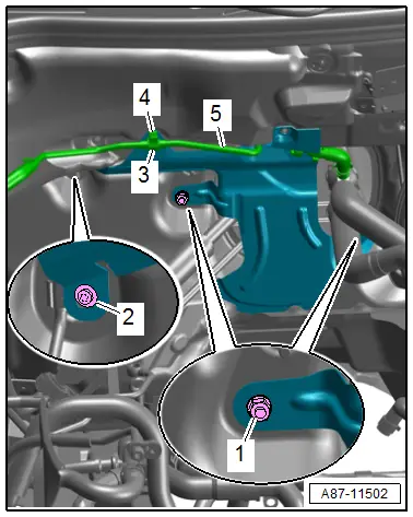
- Remove the nuts -1- and the bolt -2-.
- Open the bracket -3- and free up the coolant line -5-.
- Remove the bracket -4- from the threaded pin.
- Pry out the cable holder -4-.
- Open the bracket -1- and free up the coolant line -2-.
- Remove the heat shield -3-.
Vehicles with 4-Cylinder Engine
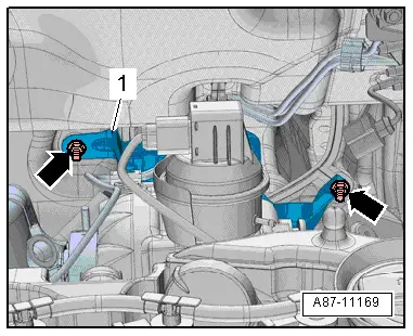
- If equipped, remove the nuts -arrows- and remove the heat shield -1-.
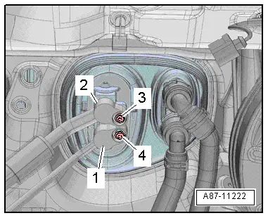
For all Vehicles
- Remove the bolts -3 and 4- and the refrigerant lines -1 and 2-.
- Seal the open lines and connections with clean plugs from the Engine Bung Set -VAS6122-.

Installing
Installation is done is reverse order, observe the following:
- Replace the O-ring seals. For the correct version, refer to the Parts Catalog.
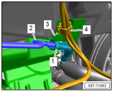
- If applicable, inspect the alignment pin -4- for damage and check that it is seated correctly.
- Inspect the guide ring -2- on the refrigerant line connection for damage.
- Insert the O-ring seal -3- into the groove -arrow- on the refrigerant line connection -1-.
 Note
Note
- Coat the O-ring seals lightly with refrigerant oil prior to installation. Refer to → Chapter "Refrigerant Circuit Seals".
- Inspect the refrigerant pipes leading to the evaporator for debris and damage.
- Check O-ring seals for proper seating in groove -arrow- of the respective refrigerant line.
- Following attachment, check routing of refrigerant lines. They must be inserted in holders provided and not make contact with other components.
- Insert the refrigerant lines -1 and 2- into the respective connection on the expansion valve.
- Tighten the bolts -3 and 4-.
- Evacuate the refrigerant circuit and fill it. Refer to → Refrigerant R134a, Servicing; Rep. Gr.87; Refrigerant Circuit (Refrigerant R134a, Servicing; Refrigerant Circuit, Using Service Station).
- Operate the A/C system after filling the refrigerant circuit. Refer to → Chapter "A/C System, Starting Operation after Filling Refrigerant Circuit".
- Check the DTC memory and erase any displayed entries using the Vehicle Diagnostic Tester in the "Guided Fault Finding" function.
READ NEXT:
 Expansion Valve, Removing and Installing
Special tools and workshop equipment
required
Engine Bung Set -VAS6122-
Removing
- Remove the refrigerant pipes from the expansion valve. Refer
to
→ Chapter "Refrigerant Line
Receiver/Dryer, Removing and Installing
WARNING
Danger due to refrigerant coming out under pressure.
Danger of frost bite to skin and other parts of the
body.
Extract the refrigerant and immediately open the
refrigerant
Dryer Bag/Dryer Cartridge, Removing and Installing
Dryer Bag/Dryer Cartridge, Removing and Installing
WARNING
Danger due to refrigerant coming out under pressure.
Danger of frost bite to skin and other parts of the
body.
Extract theSEE MORE:
Glove Compartment Handle, Removing and Installing
Special tools and workshop equipment
required
Locking Pin (3 pc.) -T40011-
Removing
Note
If glove compartment cover does not open, it can be opened
via the emergency release. Refer to
→ Chapter "Glove Compartment Lid Emergency Release, Operating".
- Press the glo
Rear Luggage Compartment Floor Handle, Removing and Installing
Special tools and workshop equipment
required
Pry Lever -80-200-
Removing
- Remove the luggage compartment floor panel.
- Release the mounting bracket -1-
from the underside of the luggage compartment floor.
- To do this position the Pry Lever -80 - 200--arrow
A-, and 