Audi Q3: Component Location Overview - Access/Start Authorization System
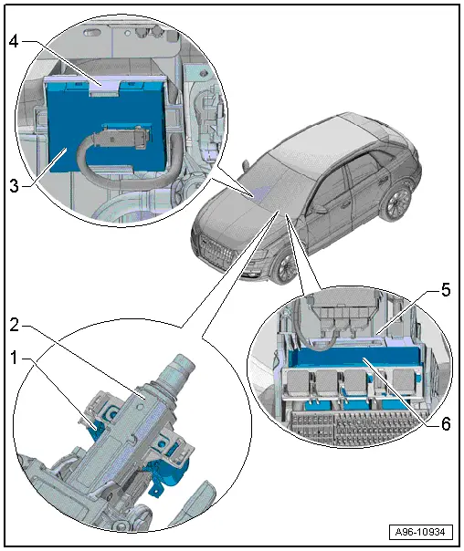
1 - Electronic Steering Column Lock Control Module -J764-
- Overview. Refer to → Chapter "Overview - Steering Column Switch Module, with Electronic Ignition Switch".
2 - Steering Column
3 - Access/Start Authorization Control Module -J518-
- Removing and installing. Refer to → Chapter "Access/Start Authorization Control Module -J518-, Removing and Installing".
4 - Bracket
- For Access/Start Authorization Control Module -J518-
5 - Mount
- For the relay and fuse panel control module
6 - Vehicle Electrical System Control Module -J519-
- With Central Locking and Anti-Theft Alarm System Antenna -R47-
- Overview. Refer to → Chapter "Overview - Instrument Panel Relay Carrier/Fuse Carrier and A-Pillar Relay Carrier/Fuse Carrier".
Component Location Overview - Keyless Access Authorization System
In the Front of the Vehicle
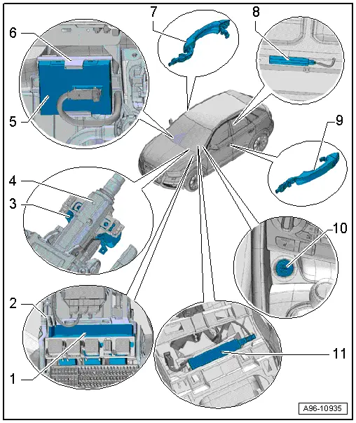
1 - Vehicle Electrical System Control Module -J519-
- With Central Locking and Anti-Theft Alarm System Antenna -R47-
- Overview. Refer to → Chapter "Overview - Instrument Panel Relay Carrier/Fuse Carrier and A-Pillar Relay Carrier/Fuse Carrier".
2 - Relay/Fuse Panel
3 - Electronic Steering Column Lock Control Module -J764-
- Removing and Installing. Refer to → Suspension, Wheels, Steering; Rep. Gr.48; Steering Column; Electronic Steering Column Lock Control ModuleJ764, Removing and Installing
4 - Steering Column
5 - Access/Start Authorization Control Module -J518-
- Removing and installing. Refer to → Chapter "Access/Start Authorization Control Module -J518-, Removing and Installing".
6 - Bracket
- For Access/Start Authorization Control Module -J518-
7 - Front Passenger Exterior Door Handle
- With the Right Front Exterior Door Handle Touch Sensor -G606-
- Overview. Refer to → Chapter "Overview - Exterior Door Handle for Keyless Access Authorization System".
8 - Access/Start System Antenna In Luggage Compartment -R137-
- Removing and installing. Refer to → Chapter "Access/Start System Antenna in Luggage Compartment -R137-, Removing and Installing".
9 - Driver Side Outside Door Handle
- With the Left Front Exterior Door Handle Touch Sensor -G605-
- Overview. Refer to → Chapter "Overview - Exterior Door Handle for Keyless Access Authorization System".
10 - Access/Start Authorization Button -E408-
- Removing and installing. Refer to → Chapter "Access/Start Authorization Button -E408-, Removing and Installing".
11 - Access/Start System Antenna 1 in Vehicle Interior -R138-
- Removing and installing. Refer to → Chapter "Access/Start System Antenna 1 in Vehicle Interior -R138-, Removing and Installing".
In the Rear of the Vehicle
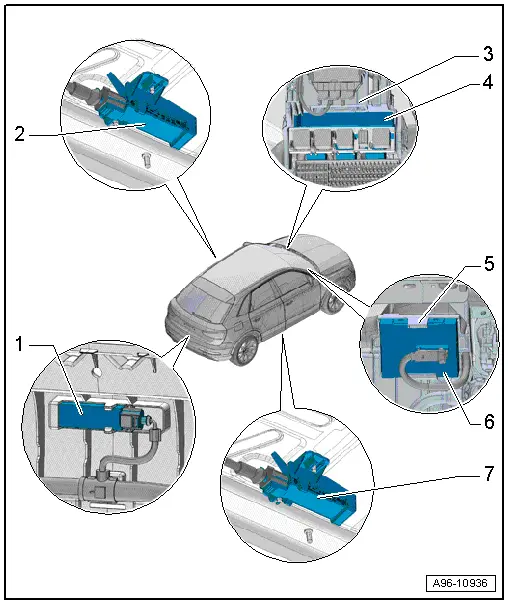
1 - Access/Start System Antenna in Rear Bumper -R136-
- Removing and installing. Refer to → Chapter "Access/Start System Antenna in Rear Bumper -R136-, Removing and Installing".
2 - Driver Access/Start System Antenna -R134-
- Removing and installing. Refer to → Chapter "Driver Access/Start System Antenna -R134-, Removing and Installing".
3 - Relay/Fuse Panel
4 - Vehicle Electrical System Control Module -J519-
- With Central Locking and Anti-Theft Alarm System Antenna -R47-
- Overview. Refer to → Chapter "Overview - Instrument Panel Relay Carrier/Fuse Carrier and A-Pillar Relay Carrier/Fuse Carrier".
5 - Bracket
- For Access/Start Authorization Control Module -J518-
6 - Access/Start Authorization Control Module -J518-
- Removing and installing. Refer to → Chapter "Access/Start Authorization Control Module -J518-, Removing and Installing".
7 - Front Passenger Access/Start System Antenna -R135-
- Removing and installing. Refer to → Chapter "Driver Access/Start System Antenna -R134-, Removing and Installing".
Overview - Exterior Door Handle for Keyless Access Authorization System
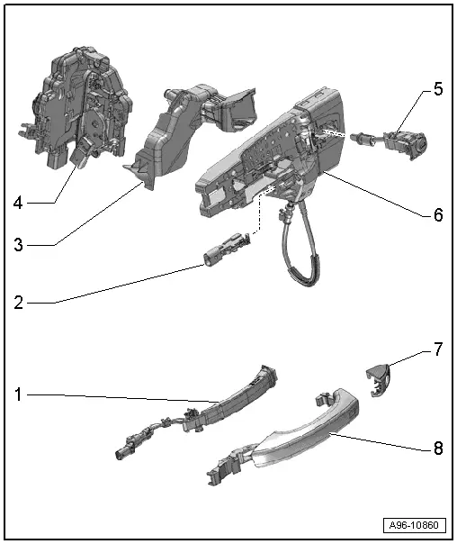
1 - Exterior Door Handle Touch Sensor
- In the outside door handle
Front door:
- Left Front Exterior Door Handle Touch Sensor -G605-, Right Front Exterior Door Handle Touch Sensor -G606-
- Removing and installing. Refer to → Chapter "Front Exterior Door Handle Switch, Removing and Installing".
2 - Not Installed
3 - Anti-Theft Cover
- For the door lock
4 - Door Lock
5 - Lock Cylinder
- Only driver's side
6 - Mounting Bracket
7 - Cap
- Driver side for the lock cylinder
- Passenger side, closed version
8 - Exterior Door Handle
READ NEXT:
 Front Exterior Door Handle Switch, Removing and Installing
Removing
- Remove the exterior door handle. Refer to
→ Body Exterior; Rep. Gr.57; Door Components; Door Handle,
Removing and Installing.
Note
Ignore -1 and 2-.
-&
Overview - Steering Column Switch Module
Steering Column Switch Module Assembly Overview, with Mechanical Ignition
Switch
1 - Steering Column
2 - Bolt
Quantity: 2
For steering lock housing (shear bolt)
3&nb
Lock Cylinder, Removing and Installing
Create an assisting tool from a wire hook as follows:
- Take a 1.5 mm diameter welding wire and bend the end to form
an eye.
- Then cut the welding wire.
Dimension -a- = approximatelSEE MORE:
Playing media
Media sources
The following sources can be selected depending
on the vehicle equipment:
Alexa
USB device
Connect external device: you can connect external
devices via Bluetooth and use the Bluetooth
audio player or you can connect
an external device directly to the USB
ports with charging
Engine compartment
General information
Special care is required if you are working in the
engine compartment
For work in the engine compartment, such as
checking and filling fluids, there is a risk of injury,
scalding, accidents, and burns. For this
reason, follow all the warnings and general
safety precautions provid