Audi Q3: Chip Card Reader Control Module, Removing and Installing
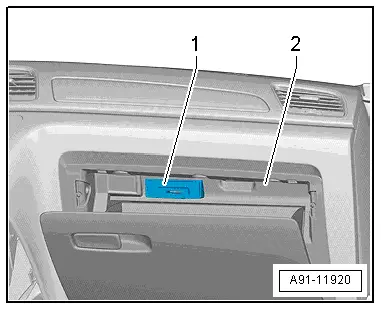
The Chip Card Reader Control Module -J676--1- is located inside the glove compartment -2-.
Removing
- Turn off the ignition and all electrical equipment and remove the ignition key.
- Remove the glove compartment. Refer to → Body Interior; Rep. Gr.68; Storage Compartment/Covers; Glove Compartment, Removing and Installing.
- Release and disconnect the connectors from the Chip Card Reader Control Module -J676-.
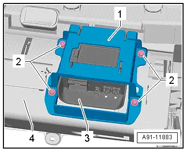
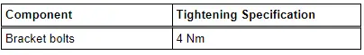
- Remove the bolts -2- from the bracket -1-.
- Remove the bracket -1- with Chip Card Reader Control Module -J676--3- from the glove compartment -4-.
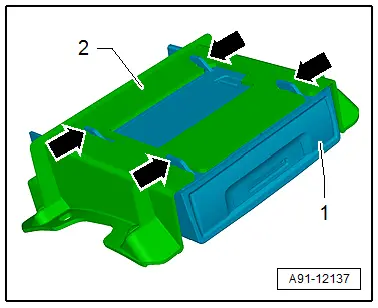
- Remove the Chip Card Reader Control Module -J676- from the bracket.
Installing
- Install in reverse order of removal. Note the following:
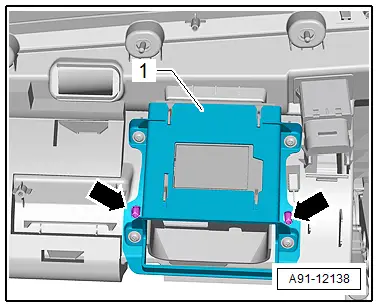
- Push the Chip Card Reader Control Module -J676--1- in the bracket -2- until it engages "audibly"-arrows-.
- Pay attention when installing the bracket -1- that the dome -arrows- on the bracket -1- are seated correctly.
READ NEXT:
 Connector Assignments, Ready4Nav 7Q4, Navigation Packet 7T2
Information Electronics Control Module 1 -J794-
1 - Connector AM/FM1 from the Antenna Amplifier -R24- (Radio
Antenna 2 -R93-)
2 - DAB connection from Antenna Amplifier 4 -R113-
Overview - Rearview Camera System
The rear view camera system assists the driver when driving
in reverse by providing the driver with an image of the traffic
situation behind the vehicle via the Front Information Display
ControlSEE MORE:
Vision
Adjusting exterior mirrors
Fig. 42 Driver's door: knob for the exterior mirrors
Turn the knob in the driver's door to the desired
position:
- Deactivates all adjustment
functions.
- Selects the left or right
exterior mirror.
To adjust the mirror glass in a mirror, press the
knob in the desired
Sill Panel Strip, Removing and Installing
Front Sill Panel Strip, Removing and Installing
Special tools and workshop equipment
required
Trim Removal Wedge -3409-
Omega Clip Tool -T40280-
Removing
- Remove the instrument panel side cover. Refer to
→ Chapter "Instrument Panel Side Cover, Removing and Installing".
-&