Audi Q3: Air Intake and Outlet Openings
Air Intake and Outlet Openings, Air Intake Housing
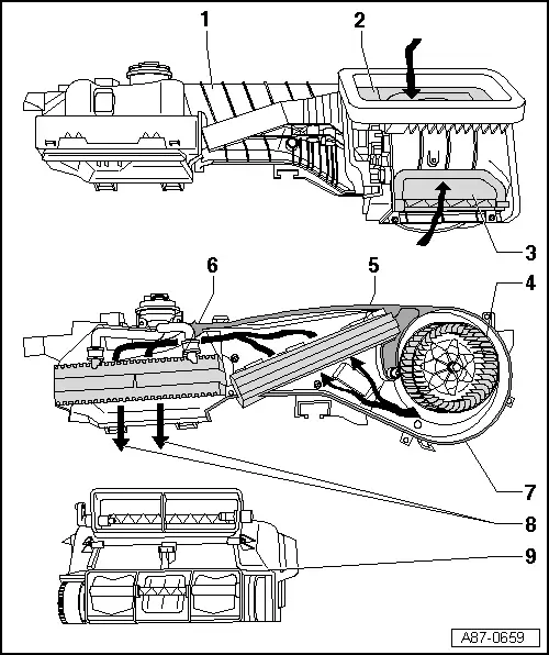
1 - Air Guide Housing
2 - Fresh Air Door
- There are different versions. Refer to the Parts Catalog.
- Only automatic climate control system
3 - Air Recirculation Door/Recirculation-/Fresh Air Door
- There are different versions. Refer to the Parts Catalog.
Manual climate control system (heater without A/C system)
- Recirculation-/fresh air door
Automatic climate control system
- Air Recirculation Door
4 - Fresh Air Blower -V2-
- There are different versions. Refer to the Parts Catalog.
- For automatic climate control system with Fresh Air Blower Control Module -J126-
5 - Dust and Pollen Filter
- There are different versions. Refer to the Parts Catalog.
- Removing and installing. Refer to → Chapter "Dust and Pollen Filter, Removing and Installing".
6 - Evaporator
7 - Evaporator Housing Lower Section
8 - To the Air Distribution Housing
9 - Air Distribution Housing
Air Intake and Outlet Openings, Heater and A/C Unit
 Note
Note
To illustrate the air routing in the air distribution housing, it is shown in the form of sectional views "A" -"A" and "B"- "B".
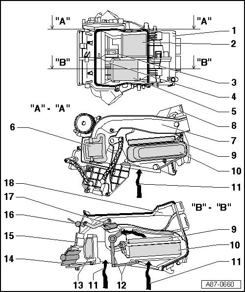
1 - Air Distribution Housing
2 - Left Temperature Door - Driver Side
- For a manual climate control system (for a heater without an Air Conditioning (A/C) system), the right and left temperature doors are connected with each other via a shaft and are moved together by the Temperature Regulator Door Motor -V68-
- For an automatic climate control system, the temperature door is moved by the Left Temperature Door Motor -V158-
3 - Air Guide
- To the air guide channel, to the vent in rear center console and to the center instrument panel vents
4 - Air Guide
- To the air guide channel, to the vent in rear center console and to the center instrument panel vents
5 - Right Temperature Door - Front Passenger Side
- For a manual climate control system (for a heater without an A/C system), the right and left temperature doors are connected with each other via a shaft and are moved together by the Temperature Regulator Door Motor -V68-
- For an automatic climate control system, the temperature door is moved by the Right Temperature Door Motor -V159-
6 - Left Footwell Door - Driver Side
- For a manual climate control system (for a heater without an A/C system), the footwell-, defroster- and central doors are connected with each other via an operating lever and are moved by the Central Air Door Motor -V70-
- For an automatic climate control system, the footwell- and central doors are connected with each other via an operating lever and are moved by the Central Air Door Motor -V70-. The defroster door is moved by the Defroster Door Motor -V107-.
7 - Air Guide Channel in Left Footwell - Driver Side
8 - Air Distribution Housing Sectioned Above Line "A"-"A"
9 - Auxiliary Heater Heating Element -Z35-
- Only installed on vehicles with a TDI engine at this time
10 - Heater Core for the Heater
11 - Air Outlet from Evaporator Housing
12 - Right Temperature Door - Front Passenger Side
- For a manual climate control system (for a heater without an A/C system), the right and left temperature doors are connected with each other via a shaft and are moved together by the Temperature Regulator Door Motor -V68-
- For an automatic climate control system, the temperature door is moved by the Left Temperature Door Motor -V158-
13 - Right Footwell Door - Front Passenger Side
- For a manual climate control system (for a heater without an A/C system), the footwell-, defroster- and central doors are connected with each other via an operating lever and are moved by the Central Air Door Motor -V70-
- For an automatic climate control system, the footwell- and central doors are connected with each other via an operating lever and are moved by the Central Air Door Motor -V70-. The defroster door is moved by the Defroster Door Motor -V107-.
14 - Defroster Door
- For a manual climate control system (for a heater without an A/C system), the footwell-, defroster- and central doors are connected with each other via an operating lever and are moved by the Central Air Door Motor -V70-
- For an automatic climate control system, the footwell- and central doors are connected with each other via an operating lever and are moved by the Central Air Door Motor -V70-. The defroster door is moved by the Defroster Door Motor -V107-.
15 - Air Distribution Housing Sectioned Above Line "B"-"B"
16 - Central Door "Center"
- For a manual climate control system (for a heater without an A/C system), the footwell-, defroster- and central doors are connected with each other via an operating lever and are moved by the Central Air Door Motor -V70-
- For an automatic climate control system, the footwell- and central doors are connected with each other via an operating lever and are moved by the Central Air Door Motor -V70-. The defroster door is moved by the Defroster Door Motor -V107-.
17 - Door in Air Guide Channel
- To the air guide for the rear center console vents
- The door is operated via an actuating arm installed to the center central door
- Depending on vehicle equipment; only for vehicles with an automatic climate control system; not visible from the outside
18 - Air Guide Channel
- To the air guide for the rear center console vents
- Depending on vehicle equipment, sealed on vehicles with a manual climate control system (for a heater without A/C system)
READ NEXT:
 Driver Side Footwell Vent, Removing and Installing
Removing
- Remove the driver side instrument panel cover. Refer to
→ Body Interior; Rep. Gr.68; Storage Compartments and Covers;
Driver Side Instrument Panel Cover, Removing
Air Distribution Channels, Removing and Installing
Center Instrument Panel Vent Air Guide, Removing and Installing
Removing
- Remove the instrument panel. Refer to
→ Body Interior; Rep. Gr.70; Instrument Panel; Instrument Pan
Passenger Compartment Forced Air Extraction, Checking
Ventilation Slots in Luggage Compartment, Checking
Test Sequence
- Check the left and right air guides through the vent
openings -arrow- built into the
luggage compartment side trim panel -
SEE MORE:
Glass Panel, Removing and Installing
Panel 1 for the Panorama Roof, Removing
Caution
Do not move or operate the already removed panel
otherwise it may become damaged.
Note
If the screws for the panel mounting were completely
removed, then they must be replaced.
1 - Bolt
7 Nm
Front and rear,
Drive Axle, Removing and Installing, Right Drive Axle with CV Joint,
Inserted with Inner Splines
Special tools and workshop equipment
required
Slide Hammer Set -VW771-
Tensioning Strap -T10038-
Puller - Driveshaft -T10382-
Torque Wrench 1332 40-200Nm -VAG1332-
Digital Torque Wrench -VAG1756A-
Removing
- Loosen the drive axle threaded connection on the wheel side.
Refer
