Audi Q3: Actuator Information
Actuator Information
 Caution
A/C system (heater) malfunctions
- A/C system malfunctions can occur if the actuator and/or the corresponding connectors are switched.
- A/C system (heater) malfunctions can occur when a connecting element (lever, gear) is interchanged or incorrectly installed on an actuator.
- Actuator connectors are identical. If these are incorrectly connected, the corresponding doors can no longer be adapted and/or activated properly.
- Various connectors that are identical in construction are present on the Air Conditioning (A/C) unit (on the heater). Mark the connectors before disconnecting them (risk of interchanging them).
- Various actuators are installed on the air distribution box and the air intake unit for the A/C unit (heater). These actuators vary in their electrical values (due to their adjusting range, specified by the different connecting elements), connecting elements and in part number. Refer to the Parts Catalog. Therefore mark the actuators before removing it (risk of interchanging).
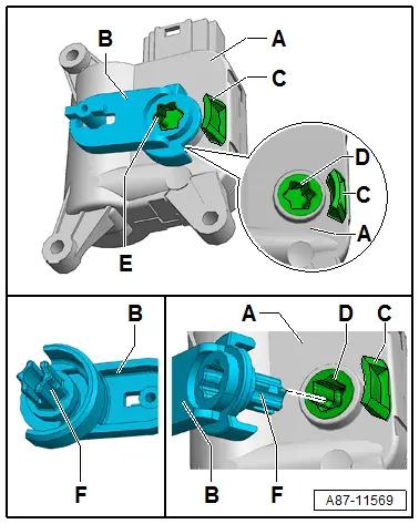
- From 10/2013 the actuators are gradually being changed. The connecting elements (lever, gears, etc., which are attached to the various actuators) to the doors in the A/C unit (heater) varied by color up to this point in time. From 10/2013 all connecting elements that are installed with the actuators to the various doors for the A/C unit (heater) are only one color (currently black). A color-coded allocation is therefore no longer possible. This illustration shows, for example, a Temperature Regulator Door Motor -V68--A- with the related connecting element (lever) -B-.
- Through 10/2013, various actuators were sent as a replacement part with a preinstalled color-coded connecting element (for example, the lever -B- to a Temperature Regulator Door Motor -V68--A-) with different part numbers. From 10/2013 as a running change, an actuator is sent as a replacement part without the connecting piece preinstalled with a set of connecting elements (for example, the lever -B- for a Temperature Regulator Door Motor -V68--A-). Refer to the Parts Catalog. Select the appropriate required connecting element from this set (depending on the version of the A/C unit / heater and on the actuator component location) and install it in the actuator shaft. Refer to → Chapter "Connecting Element, Inserting in Actuator Shaft".
- Different actuator versions without the attached connecting elements -B- were installed or delivered as a replacement part from 10/2013. The actuator version, which is installed as a Recirculation Door Motor -V113- on a heater or a manual climate control system, has no potentiometer, for example (but stop switches). There are different adjustment ranges for actuators with potentiometer (electrically valuable adjustment range maximum approximately 120º or 340º). Refer to the Parts Catalog. Ensure the correct version and allocation. If an actuator with an incorrect adjustment range is installed, it will lead to problems, for example when performing the A/C system basic setting and/or when operating the A/C system/heater. Refer to Vehicle Diagnostic Tester.
- Perform the basic setting for the A/C system after installing the actuator. Refer to Vehicle Diagnostic Tester in the "Guided Fault Finding" function.
- Using the "output diagnostic test mode" and "basic setting" functions, the activation of the electrical components for the A/C system can be checked (for example, to check for interchanging). Refer to Vehicle Diagnostic Tester in the "Guided Fault Finding" function.
- After installing a new actuator, perform the basic setting and check the activation and function of the actuator via the Climatronic Control Module -J255- control head/ A/C Control Module -J301- (the Heater Control Module -J65-). Refer to Vehicle Diagnostic Tester in the "Guided Fault Finding" function.

Connecting Element, Inserting in Actuator Shaft
 Note
Note
- Through 10/2013, various actuators were sent as a replacement part with a pre-installed color-coded connecting element (for example, the lever -B- to a Temperature Regulator Door Motor -V68--A-) with different part numbers. From 10/2013 as a running change, the various actuators are sent as a replacement part without the connecting piece pre-installed with a set of connecting elements (for example, the lever -B- for a Temperature Regulator Door Motor -V68--A-). Refer to the Parts Catalog. If necessary, select the appropriate required connecting element from the set and insert it correctly allocated into the new actuator.
- The connecting element (for example, the lever -B-) can only be installed and engaged in the shaft -D- of the actuator -A- in one position.
- The connecting elements installed in the actuators that were installed through 10/2013 (for example, lever -B-) are engaged in the shaft -D-. They can be pried out using, for example, two screwdrivers.
- So that the respective connecting element -B- can be inserted into the shaft -D- of the actuator, it must be located in the position illustrated.
Connecting Element, Inserting
- Remove the connecting element from the removed actuator (by carefully prying it out using, for example, two screwdrivers) or select the required connecting element from the set of connecting elements. Refer to Parts Catalog.
 Caution
If the wrong connecting element is selected or mounted, it may be possible to install the actuator. Problems may occur however when adapting the newly installed actuator.
- The connecting elements are to some extent very similar, therefore make sure it is the correct version.
- Only insert a connecting element that exactly matches the form of the removed connecting element.
The connecting element can be installed with the actuator despite being incorrectly assigned. Problems may occur however when adapting the newly installed actuator.
- The various actuators are identical in construction and only differ in their part number. Therefore make sure it is the correct version.
- Only install actuators that can be explicitly allocated.
 Note
Note
- The connecting elements available in the set are not color-coded. Refer to the Parts Catalog.
- The possible adjusting range of an actuator is determined by the shape of the connecting element -B- and the stop -C- on the actuator. The shaft position -D- of the actuator is determined by the respective control module via an installed potentiometer (or via a stop switch).
- Check the shaft position -D- of the actuator -A-. The shaft -F- of the connecting element can only be inserted and engaged without pretension when it is in the position illustrated.
 Note
Note
- If the shaft -D- of the actuator -A- is not located in the position illustrated (the connecting element can only be inserted in this position), activate the removed actuator so that the shaft -D- is moved into the correct position. Refer to → Chapter "Actuator, Activating using Adapter Cable".
- The connecting element -B- may only be installed in the position where it can be inserted and engaged without being forced in. The mount contour -E- of the actuator shaft -D- is stamped on various connecting elements so that the correct installation position can be better found. If pretension is needed to insert the connecting element, check the actuator shaft -D-. It can be rotated 180º.
- Do not reuse a connecting element that shows signs of wear. Replace it.
- Insert and engage the shaft of the removed or selected connecting element -F- from the delivered set into the shaft of the actuator -D-.
- Check the connecting element -B- for a secure fit in the actuator -A- .
- Install the actuator on the A/C unit (heater) at the designated position.

Actuator, Activating using Adapter Cable
 Note
Note
- For the connecting element to be able to be inserted into the shaft -D- for the actuator -A-, the shaft must be in a certain position. If the shaft -D- is in a different position than the one illustrated, it can be moved into the correct position by activating the actuator.
- The actuator shaft -D- does not have a stop. It rotates continuously on an actuator with an installed potentiometer when voltage is supplied between terminals 5 and 6 on the actuator connector. Therefore, if the connecting element -B- is connected or it cannot be connected, voltage should be applied only when the actuator has been removed in order to bring the shaft -D- into the correct position.
- If the connecting element -B- cannot be inserted into the actuator without pretension, the shaft -D- may be incorrectly positioned.
Actuator Shaft, Bringing into the Correct Position
- Connect the adapter cable (refer to → Chapter "Adapter Cable for Activating Actuators") to the actuator -A-.
 Note
Note
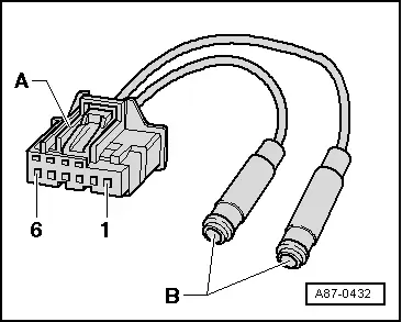
Instead of using an adapter cable, the terminals "5" and "6" (in the actuator connector -A-) can also be connected to a 12 V battery using a lead from the Connector Test Set -VAG1594D- via a 5A fuse.
- Connect one of the two adapter lines via a 5A fuse to the positive terminal, for example, of a 12 V battery.
- Briefly connect the other adapter line to the negative terminal of the 12 V battery (for example, using a lead from the Connector Test Set -VAG1594D-).
- Activate the actuator so that the shaft -D- moves to the shortest adjusting range in the illustrated position.
- Observe the actuator shaft -D- movement (rotation). If the shaft rotates in the wrong direction, the line polarity is interchanged.
- As soon as the actuator shaft -D- is in the correct position, stop the activation of the actuator.
Adapter Cable for Activating Actuators
Procedure
- Connect each of the terminals "5" and "6" on the connector -A-(Flat Terminal Housing with Auxiliary Terminal Retainer -6Q0 972 706-) to a line with a diameter of 0.25 mm2. Refer to the Parts Catalog.
- Connect the other end of each wire to a commercially available banana coupling -B-.
 Note
Note
The line can be connected to a 12 V power supply (for example, a 12 V battery) via the banana couplings -B- (using, for example, leads from the Connector Test Set -VAG1594D-).
Dust and Pollen Filter Information
Dust and pollen filter with activated charcoal filter element
The dust and pollen filter with an activated charcoal filter element is only installed on vehicles with Air Quality Sensor -G238-.
The activated charcoal filter continues to function as a dust and pollen filter, however in addition the activated charcoal filter can also filter out gaseous pollutants, for example ozone, benzene, nitrogen dioxide from the air flow. The basic task of the activated charcoal layer in the dust and pollen filter is to keep load peaks out of the passenger compartment.
The activated charcoal also has the task of removing certain gaseous contaminants from the air flowing through. The activated charcoal layer in the dust and pollen filter reacts differently to various pollutants in the air.
- Certain pollutants bond permanently in the active-carbon layer.
- Others are converted into noxious bonds like in a catalytic converter.
- For the rest the activated charcoal works as a condenser (capacitor). With increasing load pollutants are absorbed, until a certain saturation is reached. If the amount of pollutants decreases, the activated charcoal layer continuously releases the absorbed particles.
Under the following operating conditions the dust and pollen filter must be replaced earlier than required, because a certain amount of pollutant particles is permanently bonded to the activated charcoal layer.
- If the vehicle is driven in areas with heavy air pollution.
- If the vehicle is run with the "Recirculation door" off.
 Note
Note
- The active carbon layer in the dust and pollen filter is saturated after a certain time.
- A saturated filter can no longer absorb pollutants and the pollutants can flow through freely.
READ NEXT:
 Technical Data
Refrigerant R134a Capacities
Refrigerant R134a and refrigerant oil. Refer to
→ Refrigerant R134a Servicing; Rep. Gr.87; Refrigerant R134a
Capacities, Refrigerant Oil and Approved
Heating, Ventilation
Component Location Overview - Heating
Component Location Overview - Components Outside of Passenger
Compartment
Note
At the start of production, only one Air Conditioning (A/C)
syst
SEE MORE:
Central Locking
Component Location Overview - Central Locking
1 - Hood Contact Switch 2 -F329-
Inside the rear lid lock
Removing and installing. Refer to
→ Chapter "Engine Hood Contact Switch -F266-, Removing and Installing".
2 - Front Passenger Door Control Module -J387-
Air Quality Sensor -G238-, Removing and Installing
Removing
- Remove the plenum chamber cover. Refer to
→ Body Exterior; Rep. Gr.50; Bulkhead; Plenum Chamber Cover,
Removing and Installing.
- Release the securing tab -4-
and turn the housing -1- for the
Air Quality Sensor -G238- counter-clockwise
-arrow-.
-
